|
Hop up options
CSC-135 series
CENTRAL and SPEED
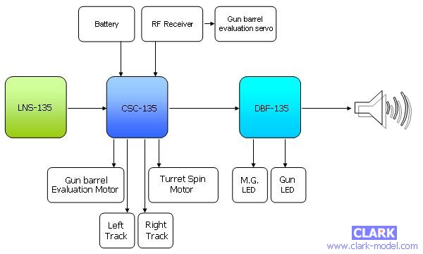
CONTROLLER: functions similar to ESC and motherboard for LNS and DBF
 CSC controller uses max.
of 4 channels to control R/C tank's forward/backward movement, sharp turning,
pivoting,
turret rotation
and
gun barrel evaluation
at variable speed
Firing control system
is controlled by 5th
channel
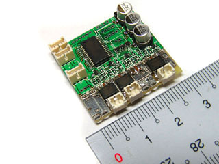
Miniature
design(30mm X 30mm) for small scale (1/25, 1/35 ,1/48 and etc.) R/C Tank
Auto
cutoff protects Li-Polymer battery from over discharged
Safety shutoff prevents
unwanted movement while signal lost
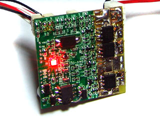
Status
LED indicates
Controller operating
status
Easy installation
To control Light and Sound
module and DBF module
DBF data build-in CSC controller uses max.
of 4 channels to control R/C tank's forward/backward movement, sharp turning,
pivoting,
turret rotation
and
gun barrel evaluation
at variable speed
Firing control system
is controlled by 5th
channel
Miniature
design(30mm X 30mm) for small scale (1/25, 1/35 ,1/48 and etc.) R/C Tank
Auto
cutoff protects Li-Polymer battery from over discharged
Safety shutoff prevents
unwanted movement while signal lost
Status
LED indicates
Controller operating
status
Easy installation
To control Light and Sound
module and DBF module
DBF data build-in
|

35
Seconds(8.7MB) |
Move forward:
Move the left
stick up
Move reverse:
Move left
stick down
Turns and pivots.: Move the right stick to left or
right to make left or right turns and pivots
|
 |
|

8
Seconds(2.0MB) |
Turret rotation: Move left stick left or right to
rotate turret. |
 |
|

4
Seconds (1 MB) |
Cannon evaluation: Move the right stick up or down
to raise or lower the cannon. |
 |
|

8
Seconds (2.2MB) |
Booming Cannon: Push safety button,
Move left stick to left |
 |
|
2
Seconds (583KB) |
Fire MG: Push safety button,
Move left stick to right |
 |
|
Part Number
|
Application
|
AFV Type
|
|
CSC-135H-L2A4
|
2-Cell
Li-Polymer or 6 Cell NI-CD operation for best performance
|
German Leopard2A4 |
|
CSC-135H-C1
|
2-Cell
Li-Polymer or 6 Cell NI-CD operation for best performance
|
U.K.
Challenger 1 |
|
CSC-135H-JP
|
2-Cell
Li-Polymer or 6 Cell NI-CD operation for best performance
|
German WWII JagdPanther |
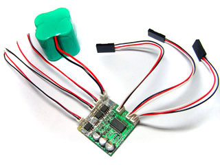
Kit contained controller*1, preassembled Battery
Cable *1, Control Cable *5 and Motor Cable *4.
|
Part Number |
Application
|
Status
|
|
Control Cable
|
To wire Servo control signal form Receiver
to
controller
|
Extra Stock |
|
Battery Cable
|
To wire Battery power form Battery to ESC.
Max. Current is
1.0A
|
Extra Stock |
|
Motor Cable
|
To wire Motor to ESC,
Max. Current is
1.0A
|
Extra Stock |
|
Charging
Cable
|
Connect Battery to Charger
|
Extra Stock |
|
Part Number
|
Parameter
|
|
Unit
|
|
CSC-135H
|
Maximum current of left and right track ESC |
2 |
A |
|
Maximum current of left and right track ESC |
2 |
A |
|
Maximum supply voltage |
7.4
|
V |
|
Minimum supply voltage |
4.8 |
V |
|
Battery-Motor Configuration
Table |
|
CSC-135H |
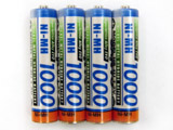
4 to 6 Cell
NI-CD |
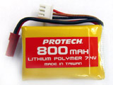
2-Cell
Li-Polymer |
|
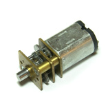
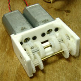
GM12
Geared Motor
|
Excellent,
Direct wire to CSC |
Excellent,
Direct wire to CSC |
|
130
Motor
Educational Serial Gear box |
Excellent
(Note
1) |
Excellent
(Note
1) |
140
Motor
1/35
W/CTank
|
Excellent
(Note
1) |
Excellent
(Note
1) |
|
260
Motor
1/25
W/C Tank |
Excellent
(Note
1) |
Excellent
(Note
1) |
|
180
Motor |
Excellent |
Excellent |
|

VS Tank Motor |
Excellent, Please refer to
Upgrade VStank
|
Excellent, Please refer to
Upgrade VStank
|
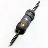
Note 1:
Wire a cement power resistor with
motor in series to avoid ESC overloading and motor overheating
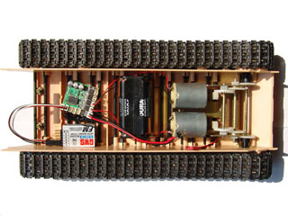
Refer to wiring diagram shown
below,
connect
Throttle(CH2),Rudder(CH1)and
Turret Rotating
(CH4) connector to
Receiver
Throttle,
Rudder
and
Turret Rotating
channel via
preassembled
Control Cables. Remove Turret
rotation control cable or keep it open if
turret rotation
is not needed.
Because
CONTROLLER
powers Receiver, battery for Receiver is unnecessary.
First turn off your
transmitter, than connect battery pack via Battery Cable,
Red wire of
Battery Cable
is + pole and Black is - pole.
If powering is in good state, Red status LED will be lit.
Turn on your transmitter,
Red status LED will be
turned off
if radio control
signal was received correctly by
CONTROLLER.
If Red status LED is sill On,
Check that your transmitter and
receiver are operating on the same frequency and check the polarity and
integrity of receiver channel signal cable connections.
If Red status LED
is flickering, that means poor or weak signaling, pull out
transmitter
antenna or adjust Receiver antenna layout.
At first time installation,
repeat previous 2 steps to make sure connection between battery, receiver and
controller are stable and correctly,
than proceed next steps.
Turn off transmitter
and disconnect battery pack form controller,
solder
preassembled
ESC1,ESC2 and ESC4 cable to left, right track and turret rotation driving
motors.
Turn on transmitter,
than connect battery pack to controller, Red
status indicator should be lit on and turned off instantly because controller
was powered than receive control signal correctly.
Adjust
throttle,
Rudder
and
Turret Rotation
channel trimmer on
transmitter
till
all motor was stopped and no hum sound was heard.
Keep
Rudder channel
stick in natural status
and move
Throttles
channel stick forward or backward,
the tank should move forward or backwardly.
if
pivoting
occurred, find out the motor which is turning in
wrong direction and
reverse its motor cable.
Adjust
Rudder trimmer
if tank can
not go straight.
|
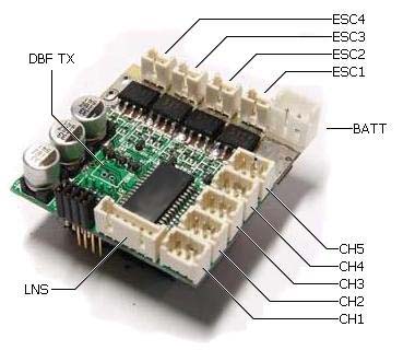
Connector
Number
|
Connector
Number
|
Remark
|
|
CH1
|
Steering control
signal
|
Wire to Receiver |
|
CH2
|
Throttle
control
signal
|
Wire to Receiver
|
|
CH3 |
Gun barrel
evaluation ESC
control
signal
|
Wire to Receiver
|
|
CH4
|
Turret rotation
control
signal
|
Wire
to Receiver
|
|
CH5 |
Firing
control system control
signal (Safety Button) |
Wire
to Receiver
|
|
DBF TX |
DBF Transmitter connector |
Connect to DBF Transmitter
|
|
DBF RX |
DBF Sensor connector |
Connect to DBF Sensor
|
|
LNS |
LNS connector |
Connect to LNS
|
|
ESC1
|
Left track ESC connector
|
Connect to Motor
|
|
ESC2
|
Right track ESC connector |
Connect to Motor
|
|
ESC3 |
Gun barrel
evaluation ESC
connector |
Connect to Motor
|
|
ESC4
|
Turret Rotating
ESC connector
|
Connect to Motor
|
|
BATT
|
Battery
connector
|
Connect to Battery
|
Top
View
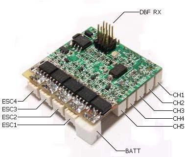
Bottom View
Build in
Mixer: Convert
Rudder and
Throttle
control
signal
to Left and
Right track speed signal.
Safety shutoff: Occurred if
controlling signal is lost, controller cuts motor off and waits signal come
back, status LED indicator will be lit.
Auto cutoff:
The motor cutoff will
occurred when battery input drops below minimum supply voltage of controller. If
cutoff is happed frequently, increasing battery cell to rise voltage or
use battery which has larger output current.
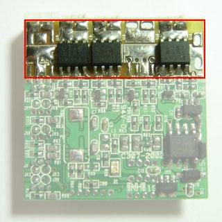
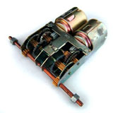
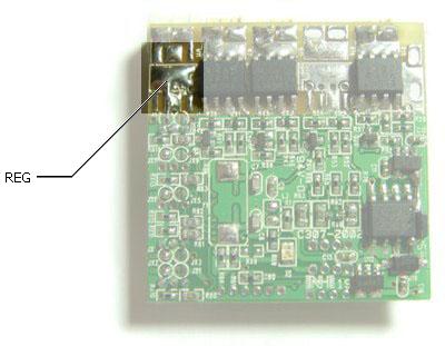
 How to identify H type or L type: Following picture is bottom view of ESC, for H
type, there has a black chip was mounted on REG decal, for L type, there
has on chip was mounted on REG decal
How to identify H type or L type: Following picture is bottom view of ESC, for H
type, there has a black chip was mounted on REG decal, for L type, there
has on chip was mounted on REG decal
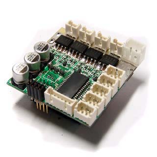
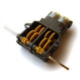
For space saving,
ESC have no external housing, please keep Controller form conductor and
metal.
Workable
with Futaba control system.
Read
carefully and fully understand the instructions before commencing assembly.
Not designed for 1/16 and larger scale R/C
Tank, please refer HOW TO Drive
380/540 Motor for more info.
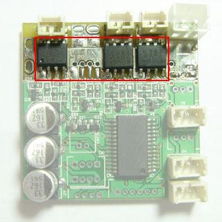
Refer to following pictures, parts circled by red frame are power FET and
regulator,
keep it from any thing for thermal diffusion.
|