|
Turret rotation and elevation FET |
FET is most easy broken parts in
control board, instantly damaged if any short circuit occurred or overstress, it
must be handled carefully.
Equipment needed

-
Soldering Iron
-
Multi-meter
-
Power supply, optional but
recommended, limit Max. current to 2A to prevent further damage during repair
work.
Compatible parts
|
Part No. |
Brand |
|
|
Si4562 |
Vishay |
|
|
SP8M4 |
Rohm |
|
|
AO4606 |
Alpha and Omega Semiconductor |
|
|
|
|
|
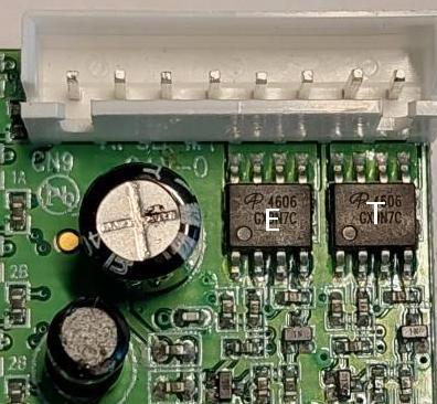
Chip
location
FETs are close to CN9
|
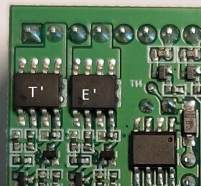
Chip annotation |
Describtion |
|
|
T |
Turret rotation Top side FET |
|
|
T' |
Turret rotation Bottom side
FET |
|
|
E |
Elevation Top side FET |
|
|
E' |
Elevation Bottom side FET |
|
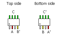
Pin
assignment and signal Table
|
Pin |
Description |
ESC off
state |
A On state |
B On state |
|
A |
Top
side FET
Low side
control |
0V |
5V |
0V |
|
A' |
Bottom
side FET
High side
control
|
~ Battery voltage |
0V |
~ Battery voltage |
|
B |
Bottom
side FET
Low side
control |
0V |
0V |
5V |
|
B' |
Top
side FET
High side
control
|
~ Battery voltage |
~ Battery voltage |
0V |
|
C |
ESC
Top side
Output |
0V |
0V |
~ Battery voltage |
|
C'
|
ESC Bottom
side
Output |
0V |
~ Battery voltage |
0V |
Step by Step
-
Visual check, turn off power,
removed all brunt FETs, remove motor from ESC port
-
Turn on power, put turret
ration/elevation stick in center position, ie. in ESC off state, use
multi-meter to measure the voltage of A, A', B, B', C, C' pins, if
reading are not the same to the number listed in ESC off state column, it means
other parts are damaged, please contact us for after market service.
-
Move turret ration/elevation
stick to one side, measure the voltage of A and B pin,
-
if A is 5V, B
is 0V, then measure A', B' pins, if reading are not the same to the
number listed in A On state column, it means other parts are damaged,
please contact us for after market service.
-
if B is 5V, A
is 0V, then measure A', B' pins, if reading are not the same to the
number listed in B On state column, it means other parts are damaged,
please contact us for after market service.
-
if A and
B are both 5V, it means other parts are damaged, please contact us for
after market service.
-
Move turret ration/elevation
stick to another side, measure the voltage of A and B pin,
-
if A is 5V, B
is 0V, then measure A', B' pins, if reading are not the same to the
number listed in A On state column, it means other parts are damaged,
please contact us for after market service.
-
if B is 5V, A
is 0V, then measure A', B' pins, if reading are not the same to the
number listed in B On state column, it means other parts are damaged,
please contact us for after market service.
-
if A and
B are both 5V, it means other parts are damaged, please contact us for
after market service.
-
If reading of A, A', B, B'
are all correct, solder new FET chip to the board.
-
Repeat step 3 and 4, now also
measure C and C' pin, If reading of A, A', B, B', C,C' are
all correct, repair is finished.
|