|
Gun Barrel Stabilizer
(GBS) The GBS is a function on GBS variant of TK series Tank Controller. When GBS is turned on, it detects the tank movement and compensate gun rotation and elevation to stabilize the gun automatically. When GBS is turned on, operator can still change gun elevation and direction under GBS compensation, GBS have the following features:
- 2-axis gun stabilization in turret rotation and gun elevation.- Fully programmable gun vertical angle calculator allows GBS to work with different elevation setup ,- Fully programmable turret motor controller allows GBS to work with different motor/gear box setup, - Engine deck detection, gun raise automatically when gun travels above engine deck,- Auto reload position, Gun barrel goes to to reload position after fire, and return to last position when reload when reload time expired, - Adjustable Engine deck level,- Adjustable auto reload position, - Gun barrel momentum effect, - GBS unit d imensions: 20 x 16 x 3mm.
Terminology
Servo for GBS
-Control System: +Pulse Width Control 1520usec
Neutral
-Operating Angle: 45 Deg. one side
Power on GBS
calibration -
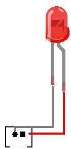
Head Light LED is turned ON during GBS calibration and you must not to move the tank during calibration. GBS unit is very sensitive and you should not touch or vibrate the GBS unit during power on reset. The process will take around 2 seconds. Head Light LED will be turned off when calibration completed. If error occurred duration calibration, such as no GBS unit connected, wrong wring, Head Light LED will not goes off
GBS LED - is a optional indicator, turned on when GBS is on An in-series 200-ohm resistor might be needed, please see GBS LED port in Connector and Pin Assignment information of each board for details
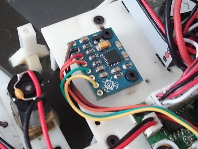
GBS unit - is sensor board needed for GBS function.
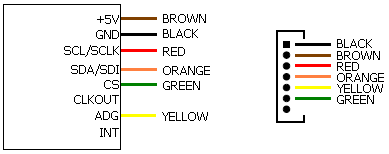
GBS unit wiring diagram
Installation
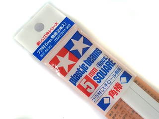
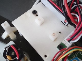
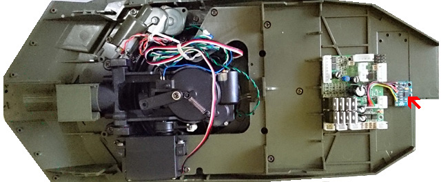
Mounting of GBS unit - The GBS unit must be mounted securely and horizontally on the turret, here is an example, first to use Tamiya 5mm square beam, cut into 5~6mm in length, make 1.6mm hole, then glue to turret floor by cement
Bolt GBS unit with the two M2 screws, and plug connector to J6 port, Length of GBS cable can not exceed 80mm or GBS data could be missed.
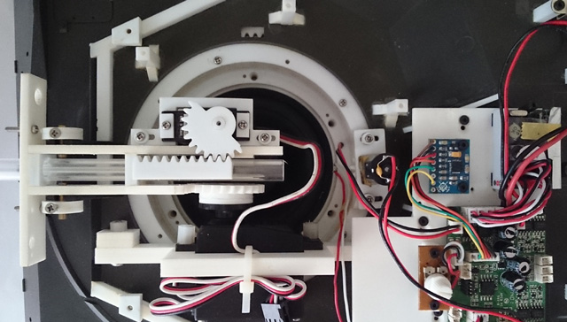
For accurate motion detection, GBS unit must be kept within 5 degree with turret base plate. mounting directions is as shown in following picture. Servo for elevation is Futaba S3003 in this setup.
Recommended GBS mounting position for Leopard 2
Turning GBS on/off - GBS can be turned on/off by Gun Barrel Stabilizer on/off commanded, you can also hear click sound when turn it on and off
Adjusting gun elevation angle - The gun elevation V gain setting is used to adjust the amount of gun elevation servo angle to meet different mechanical setup. adjusting procedures are
-First to put TK board in IR programming mode. -Turn GBS on and moves the gun barrel to horizontal position. -Tilt the tank for 15-20 degree. -Use IR configure remote to adjust servo gain value until the gun is horizontal again. -Power off TK board, remove jumper and turn power again to leave IR programming mode.
Adjusting gun elevation angle calculator gains - The angle calculator's fast gain and slow gain settings are used to adjust the angle calculation, adjusting procedures are
-First to put TK board in IR programming mode. -Turn GBS on and moves the gun barrel to horizontal position. -Tilt the tank for 10-20 degree. -Rotate turret in various speed ( from low to full speed), if elevation speed is too slow, increase slow gain a bit, otherwise, reduce slow gain, -rotate turret to 12 o'clock position, tilt the tank hull about 15-20 degree in various speed, if elevation speed is too slow, can not keep up tank hull tilt speed, increase fast gain a bit, if elevation moves faster the hull tile speed and over the position it should be (overshoot), decrease fast gain a bit -Power off TK board, remove jumper and turn power again to leave IR programming mode.
Adjusting turret rotation motor control gains -Turret rotation motor P , I and D gain are used to meet the characteristic of turret rotate motor and design on your tank. adjusting procedures are as the following.
-First to put TK board in IR programming mode. -Turn GBS on -Rotate tank hull from stationary to low speed, if turret motor does not start as quick as tank hull rotation, increase I gain a bit, if turret motor runs too fast (overshoot) , decrease I gain a bit. -Rotate tank hull in various speed( low, middle and full) , if turret rotation speed is too slow, can't keep up hull rotation, increase P gain, otherwise, reduce speed gain, -Stop tank hull rotation from various speed, if turret stops too early, decrease D gain, if turret stops too late increase D gain.
FAQs
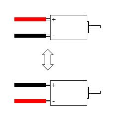
Q: When I rotate tank chassis or I move rotation stick, turret rotation start at full speed continuously and dont stop. A: Horizontal feedback loop is reversed, swap turret rotation motor cable polarity
GBS related Settings
Function Page Selection: Press "-/--" Key on IR Configuration Remote to select.
*Text in black means that setting function is on page1.
Vertical GBS slow response gain increase: Select page 3 , press number key "1" on IR Configuration Remote to increase gain
Vertical GBS slow response gain decrease: Select page 3 , press number key "4" on IR Configuration Remote to increase gain
Vertical GBS fast response gain increase: Select page 3 , press number key "2" on IR Configuration Remote to increase gain
Vertical GBS fast response gain decrease: Select page 3 , press number key "5" on IR Configuration Remote to increase gain
Vertical GBS servo angle gain increase: Select page 3 , press number key "8" on IR Configuration Remote to increase gain
Vertical GBS servo angle gain decrease: Select page 3 , press number key "0" on IR Configuration Remote to increase gain
Engine deck level increase: Select page 3 , press "VOL UP" on IR Configuration Remote to increase level Engine deck level decrease: Select page 3 , press "VOL Down" on IR Configuration Remote to decrease level Engine deck level Function Enable: Select page 3, press "MUTE" Key on IR Configuration Remote to select
Engine deck level detection switch polarity : Select page 3, press "JUMP" Key on IR Configuration Remote to select
Auto Load Position UP: Select page 3 , press "CH UP" on IR Configuration Remote to increase level
Auto Load Position Down: Select page 3 , press "CH Down" on IR Configuration Remote to decrease level
Auto Load Position Function Enable: Select page 3, press "POWER" Key on IR Configuration Remote to select
16K ESC start voltage increase: Select page 3, press "3" on IR Configuration Remote to increase level, indicator flash once each time, indicator flash twice when reach maximum level
16K ESC start voltage decrease: Select page 3 , press "6" on IR Configuration Remote to decrease level, indicator flash once each time, indicator flash twice when reach minimun level
16K ESC start voltage reset to zero: Select page 3, press "DISPLAY" Key on IR Configuration Remote to reset start voltage, indicator flash once every time.
Horizontal GBS motor P gain increase: Select page 4 , press number key "1" on IR Configuration Remote to increase gain
Horizontal GBS motor P gain decrease: Select page 4 , press number key "4" on IR Configuration Remote to increase gain
Horizontal GBS motor I gain increase: Select page 4 , press number key "2" on IR Configuration Remote to increase gain
Horizontal GBS motor I gain decrease: Select page 4 , press number key "5" on IR Configuration Remote to increase gain
Horizontal GBS motor D gain increase: Select page 4 , press number key "3" on IR Configuration Remote to increase gain
Horizontal GBS motor D gain decrease: Select page 4 , press number key "6" on IR Configuration Remote to increase gain
Turret ESC dead band increase: Select page 4 , press number key "8" on IR Configuration Remote to increase gain
Turret ESC dead band decrease: Select page 4 , press number key "0" on IR Configuration Remote to increase gain
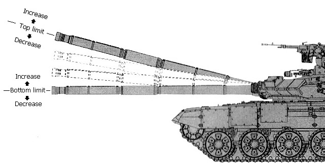
Servo elevation range adjustment: For tank with smaller elevate range, following settings can be used to set top and bottom limit to define elevation range
Top limit increase: Select page 4, press "VOL UP" on IR Configuration Remote to increase level
Top limit decrease: Select page 4 , press "VOL Down" on IR Configuration Remote to decrease level
Bottom limit increase: Select page 4, press "CH UP" on IR Configuration Remote to increase level
Bottom limit decrease: Select page 4 , press "CH Down" on IR Configuration Remote to decrease level
Servo elevation range reset: Select page 4 , press "MUTE" key on IR Configuration Remote to set to full range
|
||||||||||||||||||||||||||||||||||||||||||||||||||||||||||||||||||||||||||||||||||||||||||||||||||||||||||||||||||||||||||||||||||||||||||||||||||||||||||||||||||||||||||||||||||||||||||||||||||||||||||||||||||
|
|