Field Tank Training System ( FTTSTM) 
The Field Tank Training System is software package, can be
installed in all TK series RC tank control board to achieve a radio Controlled,
cost-effective tank training system for single tank or tank platoon maneuver, it
has the following features:
- Support Single-crew or 2-crew control
scheme,
Task of each role in 2-Crew
control scheme are listed below
|
Version |
TTK |
TCK |
|
V1 release |
Co. + Gunner
|
Driver |
|
V2 release |
Preliminary : Gunner
secondary
:RWS
|
Preliminary :
Co. + Driver
secondary
:RWS
|
|
V2.1 release |
On-the-Fly GBS sensor calibration feature added |
|
- When
receiver is not connected to TCK, FTTS is in Single-crew mode,
-
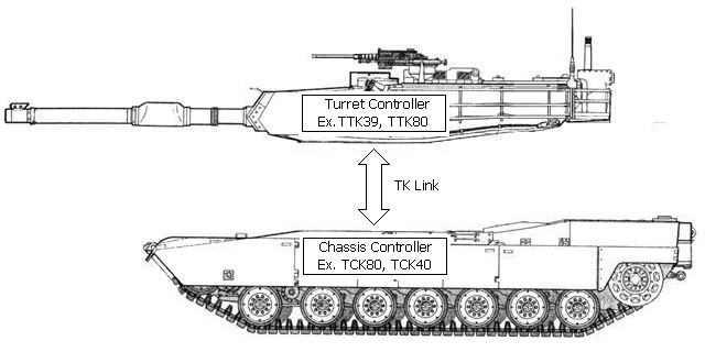
Turret controller, installed in turret, controls turret
movements, sounds and light effect,
-
Chassis controller, installed in chassis. controls chassis
movements, sounds and light effect,
- Turret controller and Chassis controller
communicate to each other by a two-wire Link, named TK Link,
- G variant Turret controller
supports GBS
- ( V2 release ) Support 60A
turret rotation ESC, adjustable start voltage.
-
Maximum of 10 channel of
sound effect can be generated at the same
time, such as
-
Main gun
-
Main gun
reload
-
Machine
gun
-
Coaxial
machine gun
-
Hull
mount machine gun( for WWII tank)
-
Turret
rotation
-
Main gun
elevation and depression
-
Turret
rotation
-
Engine
start
-
Engine
revving
-
Engine
stop
-
Turn
indicator
-
Horn(
for Leopard II tank)
-
Incoming( for IR battle)
-
Hit( for
IR battle)
-
Destroyed( for IR battle)
-
MG
incoming
-
MG Hit
-
Hydraulic sound( for ESC3 and ESC4 on Chassis control board )
-
Different Turret and Chassis controller can be mixed and work together, such as
TTK24+TCK60.
- 4
additional ESCs, 2 of them have sound effects
- Only
need 12-wire or 8-wire 2A-curret slip ring for 360 degree rotation
| Tank /
Configuration |
Slip ring type
and pin assignment |
|
Configuration
1
-
Turret speaker, Turret rotation and engine deck
switch in turret
-
Use 8-wire slip ring, 6 wire for power, 2 wire for TK Link
-
Battery - is
always needed when TTK and TCK are powered by different battery to make
TTK and TCK are not floating to each other.
|
Use 8-wire slip ring
-
Battery +
-
Battery +
-
Battery +
-
Battery -
-
Battery -
-
Battery -
-
TK-Link RX
-
TK-Link TX
|
|
Configuration
2
-
Turret speaker in Chassis, turret rotation and
engine deck switch in turret, such as Tamiya Leopard 2
-
Use 12-wire slip ring, 8 wire for power, 2 wire
for TK Link, 2 wire for turret speaker
-
Battery - is
always needed when TTK and TCK are powered by different battery to make
TTK and TCK are not floating to each other
-
configuration in our RTR Tank.
|
Use
12-wire slip ring
-
Battery + (Red)
-
Battery + (Yellow)
-
Battery + (Orange)
-
Battery + (Pink)
-
Battery - (Blue)
-
Battery - (Light
Blue)
-
Battery - (Gray)
-
Battery - (Black)
-
TK-Link RX (Purple)
-
TK-Link TX (White)
-
Turret Speaker +(Brown)
-
Turret Speaker - (Light Green)
|
Configuration 3, HL
stock tank
-
Turret rotation and engine deck switch in chassis, such as Heng Long Tank.
-
Use 12-wire slip ring, 6 wire for power, 2 for TK Link, 2 for Turret
rotation motor, 2 for engine deck switch
-
Battery - is
always needed when TTK and TCK are powered by different battery to make
TTK and TCK are not floating to each other.
|
Use
12-wire slip ring
-
Battery +
-
Battery +
-
Battery +
-
Battery -
-
Battery -
-
Battery -
-
TK-Link RX
-
TK-Link TX
-
Turret rotation Motor +
-
Turret rotation Motor -
-
Engine deck switch
-
Engine deck switch
|
Terminology
TK Sound
pack is created by combing Pack Header, sound effect data
region and region mark, can be modified and simulate sound effect
result in most of Audio editing tool on the market easily, no
extra tool to install and learn, can be adapted in TK20, TK30 and TK60 series
control board and therefore named TK sound pack
S.BUS
is a serial interface that can carry up to 16 channel data.
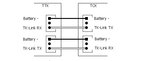
TK-LINK
is a serial interface for the
communication between
turret
controller (TTK) and Chassis controller (TCK) ,
TK-LINK RX pin receives commands,
TK-LINK TX pin transmits commands,
connection between TCK and TTK is as followed diagram.
TK-LINK RX Indicator
is a LED to show the status of data receiving,
when data is received correctly, it's turned off, when data is NOT
received correctly, it's turned ON
TBU FLASH LED
is LED on Tamiya battle unit or IR configuration Line
, which
indicate the IR battle status or the setting
just set during
Tank Personalization
Rotating Light
are LEDs which is turned on and off sequentially ,
LED1 ON --> LED1 Off --> LED2 ON --> LED2 Off --> LED3 ON --> LED3 Off -->
LED1 ON ........
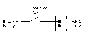
Controlled Switch
is a power port which can be closed or opened by
user command, following is the equipment diagram
EPM (
ESC/PWM module) is
peripheral which can be switched to
ESC or PWM mode, allows the user to
drive
brushed motor or servo motor, in ESC mode, ESC port is enabled, can be used to
drive brushed motor, In PWM mode, PWM port is enabled to driver servo motor,
sound effect stopped when servo motor reach end point,
ESC port of EPM No. is
represented as
EPM No. .ESC, such as EMP1.ESC
PWM port of EPM No. is
represented as
EPM No. .ESC, such as EMP1.PWM
IR Battle Emitter
Port
to connect IR emitter LED to transmit IR beam.
TBU FLASH LED
are LEDs to show IR battle status, such as got
hit from other tank.
HL battle unit has no
TBU FLASH LED on it, need to connect a LED to this
port.
AMP
is amplifier in short
RWS
is Remote Weapon Station in short
Hazard
Light
Left and Right
Blinker are both turned on
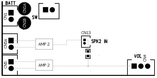
External audio input ( SPK2 IN )
allow another audio signal to connect to input of AMP2, by
default, a 0-ohm resistor is used to connect input of AMP2 to CN4 pin 1, to
remove it to separate when connecting another audio signal to AMP2.
Hit taken from back cause more
damage because tank has less protection in back, a Mini battle unit
is connected to TCK.CN2 port to sense hit from back.
Damage level of Hit taken from back setting determines how many
hits taken equal to single hit taken from back.
Type of Tank
determines
Battle Date when doing IR battle( See
Variants section
)
|
Type of
Tank
|
Tank
Mobility,
Turret rotation and Gun barrel evaluation speed
vs.
Hit taken |
|
Damaged
State |
Badly Damaged
State |
Destroyed
State |
|
Heavy Tank* |
1~4
hits taken |
5~8
hits taken |
9
hits taken |
|
Medium
Tank |
1~3
hits taken |
4~5
hits taken |
6
hits taken |
|
Light Tank |
1
hit taken |
2
hits taken |
3
hits taken |
|
HL Tank |
1~2
hits taken
(Note) |
3~4
hits taken
(Note) |
5
hits taken |
Note:
HENG-LONG TANK doesn't have Damaged State and Badly Damaged State. speed
reduction can be turned off by
Speed reduction in damage state and Speed
reduction in badly damaged state
function.
|
Type of
Tank
|
Reload Time
|
Recovery Time
|
Invulnerability time |
|
Heavy Tank* |
9 sec. |
15
sec. |
10
sec. |
|
Medium
Tank |
5 sec. |
15
sec. |
12
sec. |
|
Light Tank |
3 sec. |
15
sec. |
15
sec. |
|
HL
Tank |
3 sec.(Note) |
15
sec. |
10
sec.(Note) |
Note:
Suggested Value, can be changed by Reload Time and
Invulnerability time setting function
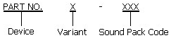
Product
Identification System
| Device |
TTK80 |
TTK80 series
Turret controller |
| |
TTK50 |
TTK50 series
Turret controller |
| |
TTK39 |
TTK39 series
Turret controller |
| |
TCK80 |
TCK80 series
Chassis controller |
| |
TCK50 |
TCK50 series
Chassis controller |
| |
TCK39 |
TCK39 series
Chassis controller |
| |
TK5050 |
TCK50 +
TTK50 |
| |
TK8039 |
TCK80 +
TTK39 |
| |
TK8050 |
TCK80 +
TTK50 |
| |
TK8080 |
TCK80 +
TTK80 |
| |
|
|
|
Variant |
Blank |
Standard |
| |
S |
Support
S.BUS interface |
| |
P |
Sound
Programmable |
| |
G |
Support
dual-axial Gun Stabilizer |
| |
W |
With
preordered wire on CN1A, CN1B, CN6A, CN6B, CN7A and CN7B pads |
| |
A1 |
105A track
motor current |
| |
V |
Software version |
| |
X |
Use external ESC for
track motor |
| |
E |
Extend Sound effects |
| |
|
|
|
Sound Pack |
T1 |
Tiger I |
| |
KT |
King Tiger |
| |
CH2_V1 |
Challenger 2
ver. 1 |
| |
..... |
Refer to TK Sound Pack webpage for more
information |
Convention Annotation
Ports, Pins are sometimes
annotated by " ( Device.peripheral.port.pin
) " format, for example:
(TTK.EPM2.ESC.Pin1) means Pin 1 of EMP2 on TTK board
(TCK.CN6
) means CN6 port on TCK board
Variants
|
Supported Hardware
|
All TK series
|
|
Remote Control
System
|
10-CH 2.4G RC system w/ S.BUS |
|
User Sound Programmability
|
YES |
|
User Tank Personalization
Programmability |
YES |
|
TAMIYA IR battle
Compatible |
YES |
|
HL IR battle Compatible
|
YES |
|
VsTank IR battle
Compatible
|
YES |
|
TAMIYA 1/35 IR battle Compatible |
YES |
|
Damage Simulation on track
|
YES |
|
Damage
Simulation on
turret
rotation and gun elevation |
YES |
|
Long
range IR battle
(>30M) |
YES
|
|
Maximum sound track |
8 |
|
Engine Sound Simulation
|
Multi-Sample-Set, Multi-Channel Mixing,
Frequency Shift and Level, Real-Time Revving |
|
Sound set for specific tank model |
YES |
|
Track driver Current
|
TCK60,TCK80:60A
TCK60A1,TCK80:100A
TCK20:20A
TCK40:20A
TCK50:20A
TCK30:7A |
|
Track driver Momentum
Effect
with ON/Off Control |
YES |
|
Turret Rotation Speed Control |
YES |
|
Gun Elevation Speed Control
|
YES |
|
Gun Elevation Servo Port
|
YES |
|
2nd MG sound and Light
effect
|
YES |
|
3rd MG sound and Light
effect
|
YES |
|
AirSoft with Sound Synchronization support |
YES |
|
HL
Recoil unit support
|
YES |
|
TAMIYA
Recoil Unit Support |
YES |
|
RealRecoil Port |
YES |
|
Smoker Pre-heating |
YES |
|
Proportional
Smoker driver |
YES |
|
Head Light on/off control |
YES |
|
Tank Personalization |
YES |
|
LED gun flash Port |
YES |
|
Chassis
Recoil On/Off
Control
|
YES |
|
Vertical Gun Barrel Stabilizer |
YES |
|
Turret Heading-Hold
(Horizontal Gun
Barrel
Stabilizer)
|
G3 version |
|
Auto Load Position |
G3 version |
|
Engine Deck Level Detection |
G3 version |
|
Additional ESC with sound effect |
2 |
|
Additional ESC without sound effect
|
2 |
|
Preload sound pack |
M1 Abrams |
*Existing TK80/TK60/TK24/TK39 series board
can be loaded with Turret or Chassis control software to be turret or Chassis
controller for free
Hardware
Variants
Track FET and audio amplifier
can be upgraded per order
|
Version |
Description/Notice/Change/New
Features |
Release Schedule |
|
- |
Standard Specification
|
Released |
|
A1 |
100A track current, Class-D 35W Audio
amplifier
|
Per-Order |
|
|
|
|
|
|
|
|
Release Schedule
|
Software
Package
Name |
Description/Notice/Change/New
Features |
Release Schedule |
|
V1 |
Initial Release, For TK60 Board
|
Released |
|
V1 |
Initial Release, For TK39 Board
|
Released |
|
V2 |
2nd release For TK50/40/39/80/60 Board
-
Support 60A turret rotation ESC, turret rotation
port is moved to TTK.CN7 to support high speed high current rotation unit
-
New control scheme to support RWS and allow Crew
1 to focus on gunner functions
-
RWS
-
TTK.Main-RWS switch is added to TTK
to select Main gun or RWS control
-
TCK.MG-RSW switch
is added to TCK to select TTK.MG or RWS control
-
TTK.EPM3 for RWS
rotation
-
TTK.EPM4 for RWS elevation
-
TTK.MG2
for RWS LED
-
Both Crew 1 and Crew 2 can access
to RWS, but Crew1 has priority
|
Released |
|
V3 |
3rd release for
TK50/40/39/80/60 Board
- V3 engine
sound simulation,
- V3 sound
pack, same sound pack is used for TK, TTK and TCK,
- High
speed vertical GBS driver, new algorithm of angle calculation is introduced.
delay to simulate GBS response on real tank is removed.
-
On-The-Fly GBS calibration, not only power-on calibration, but now it can be
performed any time.
-
8 Ext. Sound Effects
supported on TTK, can be triggered independently,
-
Wider motor start voltage adjustable range to meet different motor,
-
Hit taken from back function added.
-
Adjustable Auto load position delay and duration
-
Auto Load position and engine deck level is now supported on non-GBS variant
|
Released
2023/03/07 |
|
|
|
|
Boot loader Release
Boot Loader is a application, executed in TK
board, to handles software update, sound pack programming and setting data
update
|
Version |
Description/Notice/Change/New
Features |
Release Schedule |
|
Ver.2
|
-Auto Sound pack change detection
-Auto Clean at software update |
Released |
Ordering Information
Complete package:
|
Item No. |
Kit
Contained |
|
|
TK6039SP |
|
|
|
TK8039SPG |
|
|
|
TK6060SPG |
|
|
|
TK8080SPG |
|
|
|
TK5050SP |
|
|
Single board:
|
Item No. |
Kit
Contained |
|
|
TTK80SPG |
|
|
|
TTK60SPG |
|
|
|
TTK24SPG |
|
|
|
TTK39SPG |
|
|
|
TTK50SPG |
|
|
|
TTK60SP |
|
|
|
TTK24SP |
|
|
|
TTK39SP |
|
|
|
TTK50SP |
|
|
|
TCK80SP |
|
|
|
TCK60SP |
|
|
|
TCK24SP |
|
|
|
TCK39SP |
|
|
|
TCK40SP |
|
|
|
TCK50SP |
|
|
|
GTK39SPG3 |
|
|
|
|
|
|
Turret Control Scheme,
Co./Crew 1
Based on FS-i6S
Radio, Stick Mode is M1
V1 Release
|
  |
TCK Driver on:
(TTK.EPM3) Throttle
TCK Driver off:
Tank Right
and Left turn
TCK上的獨立駕駛功能啟動:
(TTK.EPM3)
油門
TCK上的獨立駕駛功能關閉:
戰車左右轉向
|
CH1 (Stick) |
|
 |
TCK Driver on:
(TTK.EPM4) Throttle
TCK Driver off:
Tank move forward and backward
TCK上的獨立駕駛功能啟動:
(TTK.EPM4)
油門
TCK上的獨立駕駛功能關閉:
戰車前進後退
|
CH2 (Stick) |
|
|
Cannon elevation/ (TTK.EPM1)
throttle
主砲俯仰/(TTK.EPM1)
油門 |
CH3
(Stick) |
|
|
Turret rotation/(TTK.EPM2)
throttle
砲塔迴轉/(TTK.EPM2)
油門
|
CH4
(Stick) |
|
SwA |
UP:
Aux Light 1 Off
DW:
Aux Light 1 On
撥桿向上:輔助燈2
關
撥桿向下:輔助燈2
開
|
assign SwA to CH5 |
|
SwB: Up
SwC: Center -> Up
|
TCK Driver on: (TTK.EPM3)
& (TTK.EPM4) safety On/Off
TCK Driver off:
Natural Gear Shift In/Out
TCK上的獨立駕駛功能啟動:
(TTK.EPM3) & (TTK.EPM4)安全開關
TCK上的獨立駕駛功能關閉:
履帶馬達安全開關
|
assign SwB to CH7
assign SwC to CH8 |
|
SwB: UP
SwC: Center -> Down
|
TCK Driver on: N/A
TCK Driver off:
Engine start/stop
TCK上的獨立駕駛功能啟動:
無功能
TCK上的獨立駕駛功能關閉:
引擎音效啟動
|
assign SwB to CH7
assign SwC to CH8 |
|
SwB: Center
SwC: Center -> Up
|
TCK Driver on: N/A
TCK Driver off:
TCK.Left Blinker
TCK上的獨立駕駛功能啟動:
無功能
TCK上的獨立駕駛功能關閉:
左方向燈
|
assign SwB to CH7
assign SwC to CH8 |
|
SwB: Center
SwC: Center -> Down
|
TCK Driver on: N/A
TCK Driver off:
TCK.Right Blinker
TCK上的獨立駕駛功能啟動:
無功能
TCK上的獨立駕駛功能關閉:
右方向燈
|
assign SwB to CH7
assign SwC to CH8 |
|
SwB: Down
SwC: Center -> UP
|
TTK39/50
TCK Driver on: N/A
TCK Driver off:
TCK.Hazard Light On/Off
TCK上的獨立駕駛功能啟動:
N/A
TCK上的獨立駕駛功能關閉:
警示燈.駐車燈開關(左右方向燈同時閃爍)
TTK80/60
TCK Driver on: TTK.Controlled
SW ON/OFF
TCK Driver off: TTK.Controlled
SW ON/OFF
TCK上的獨立駕駛功能啟動:
控制開關 開/關
TCK上的獨立駕駛功能關閉:
控制開關 開/關
|
assign SwB to CH7
assign SwC to CH8 |
|
SwB: Down
SwC: Center -> Down |
TTK39/50
Driver on: N/A
Driver off:
Head
light On/Off
TCK上的獨立駕駛功能啟動:
無
TCK上的獨立駕駛功能關閉:
頭燈開/關
TTK80/60
Driver on:
Rotating Light On/Off
Driver off:
Head
light On ->
Rotating Light On ->
Head
light Off->
Rotating Light Off ->Head
light On
TCK上的獨立駕駛功能啟動:
迴轉燈 開/關
TCK上的獨立駕駛功能關閉:
頭燈開 -> 迴轉燈開
->頭燈關 -> 迴轉燈關
|
assign SwB to CH7
assign SwC to CH8 |
|
SwD |
UP:
Aux Light 2 Off
DW:
Aux Light 2 On
撥桿向上:輔助燈2
關
撥桿向下:輔助燈2
開
|
assign SwD to CH6 |
|
VrA |
UP:
Gun Barrel
Stabilizer on/off
MID:
DW:
Fire
TTK.MG2(
Ex. Co. or
Weapon Station)
DW:
N/A
轉輪往上:
主砲穩定功能 開/關
轉輪往下: 第二路機槍射擊
|
assign VrA to CH9 |
|
VrB |
UP:
Booming Cannon
MID:
DW:
Fire
TTK.MG1(
Ex. Coaxial MG)
轉輪往上:
主砲射擊
轉輪往下: 機槍射擊
|
assign VrB to CH10 |
|
TTK V2 Release,
Single crew mode,
Crew 2 is off or TCK radio is not connected
|
|
Tank Right
and Left turn
|
CH1 (Stick) |
|
|
Tank move forward and backward
|
CH2 (Stick) |
|
|
TTK.SwA Up :Cannon
elevation/ (TTK.EPM1) throttle
TTK.SwA down:
(TTK.EPM4) Throttle ( RWS elevation)
TTK.SwA 上 :主砲俯仰/ (TTK.EPM1) 油門
TTK.SwA 下:
(TTK.EPM4)
油門 ( RWS elevation)
|
CH3
(Stick) |
|
|
TTK.SwA Up:
Turret rotation/(TTK.EPM2)
throttle
TTK.SwA down:
(TTK.EPM3) Throttle ( RWS rotation )
TTK.SwA 上 :砲塔迴轉/(TTK.EPM2)
油門
TTK.SwA 下:
(TTK.EPM3)
油門 ( RWS rotation )
|
CH4
(Stick) |
|
SwA |
Main-RWS
Switch
UP:
Switch to Main gun
Down
:Switch
to RWS
|
assign SwA to CH5 |
|
SwB: Up
SwC: Center -> Up
|
Natural Gear Shift In/Out
履帶馬達安全開關
|
assign SwB to CH7
assign SwC to CH8 |
|
SwB: UP
SwC: Center -> Down
|
Engine start/stop
引擎音效啟動 |
assign SwB to CH7
assign SwC to CH8 |
|
SwB: Center
SwC: Center -> Up
|
Left
Blinker
左方向燈
|
assign SwB to CH7
assign SwC to CH8 |
|
SwB: Center
SwC: Center -> Down |
Right Blinker
右方向燈 |
assign SwB to CH7
assign SwC to CH8 |
|
SwB: Down
SwC: Center -> UP |
TCK.Hazard Light On/Off
警示燈.駐車燈開關(左右方向燈同時閃爍) |
assign SwB to CH7
assign SwC to CH8 |
|
SwB: Down
SwC: Center -> Down |
TTK39/50
TCK.Head
light On/Off
TCK上的獨立駕駛功能關閉:
頭燈開/關
TTK80/60
TCK.Head
light On ->
TTK.Rotating Light
On ->
TCK.Head
light Off-> TTK.Rotating
Light
Off ->TCK.Head
light On
TCK上的獨立駕駛功能關閉:
頭燈開 -> 迴轉燈開
->頭燈關 -> 迴轉燈關
|
assign SwB to CH7
assign SwC to CH8 |
|
SwD |
UP:
TTK.Aux Light 2 Off
DW:
TTK.Aux Light 2 On
撥桿向上:輔助燈2
關
撥桿向下:輔助燈2
開
|
assign SwD to CH6 |
|
VrA |
UP:
Gun Barrel
Stabilizer on/off ( GBS version )
UP and last more than 3 seconds: GBS
calibration
轉輪往上:
主砲穩定功能 開/關
轉輪往上超過3秒鐘:
執行GBS校正
DW:
轉輪往下: 第二路機槍射擊
|
assign VrA to CH9
V2.1 and above release |
|
VrB |
UP:
Booming Cannon
MID:
DW:
Fire
TTK.MG1(
Ex. Coaxial MG)
轉輪往上:
主砲射擊
轉輪往下: 機槍射擊
|
assign VrB to CH10 |
TTK V3 and V3 E
variant Release,
Single crew mode,
Crew 2 is off or TCK radio is not connected
|
|
Tank Right
and Left turn
|
CH1 (Stick) |
|
|
Tank move forward and backward
|
CH2 (Stick) |
|
|
TTK.SwA Up :Cannon
elevation/ (TTK.EPM1) throttle
TTK.SwA down:
(TTK.EPM4) Throttle ( RWS elevation)
TTK.SwA 上 :主砲俯仰/ (TTK.EPM1) 油門
TTK.SwA 下:
(TTK.EPM4)
油門 ( RWS elevation)
|
CH3
(Stick) |
|
|
TTK.SwA Up:
Turret rotation/(TTK.EPM2)
throttle
TTK.SwA down:
(TTK.EPM3) Throttle ( RWS rotation )
TTK.SwA 上 :砲塔迴轉/(TTK.EPM2)
油門
TTK.SwA 下:
(TTK.EPM3)
油門 ( RWS rotation )
|
CH4
(Stick) |
|
SwA |
Gun
selection
UP:
Main gun
Down
: RWS
|
assign SwA to CH5 |
|
SwB: Up
SwC: Center -> Up
|
Natural Gear Shift In/Out
履帶馬達安全開關
|
assign SwB to CH7
assign SwC to CH8 |
|
SwB: UP
SwC: Center -> Down
|
Engine start/stop
引擎音效啟動 |
assign SwB to CH7
assign SwC to CH8 |
|
SwB: Center
SwC: Center -> Up
|
Left
Blinker
左方向燈
|
assign SwB to CH7
assign SwC to CH8 |
|
SwB: Center
SwC: Center -> Down |
Right Blinker
右方向燈 |
assign SwB to CH7
assign SwC to CH8 |
|
SwB: Down
SwC: Center -> UP
|
TCK.Hazard Light On/Off
警示燈.駐車燈開關(左右方向燈同時閃爍) |
assign SwB to CH7
assign SwC to CH8 |
|
SwB: Down
SwC: Center -> Down |
TTK39/50
TCK.Head
light On/Off
TCK上的獨立駕駛功能關閉:
頭燈開/關
TTK80/60
TCK.Head
light On ->
TTK.Rotating Light
On ->
TCK.Head
light Off-> TTK.Rotating
Light
Off ->TCK.Head
light On
TCK上的獨立駕駛功能關閉:
頭燈開 -> 迴轉燈開
->頭燈關 -> 迴轉燈關
|
assign SwB to CH7
assign SwC to CH8 |
|
SwD |
UP:
TTK.Aux Light 2 Off
DW:
TTK.Aux Light 2 On
撥桿向上:輔助燈2
關
撥桿向下:輔助燈2
開
|
assign SwD to CH6 |
|
VrA |
UP:
Gun Barrel
Stabilizer on/off ( GBS version )
UP and last more than 3 seconds: GBS
calibration
轉輪往上:
主砲穩定功能 開/關
轉輪往上超過3秒鐘:
執行GBS校正
DW:
轉輪往下: 第二路機槍射擊
|
assign VrA to CH9 |
|
VrA
SwB: Up |
UP:
Gun Barrel
Stabilizer on/off ( GBS version )
UP and last more than 3 seconds: on-the-fly GBS
calibration
轉輪往上:
主砲穩定功能 開/關
轉輪往上超過3秒鐘:
執行GBS校正
DW:
轉輪往下: 第二路機槍射擊
|
assign VrA to CH9
( V3 E variant ) |
|
VrA
SwB: Center |
UP:
Ext Sound Effect 1
MID:
DW:
Ext Sound Effect 2
|
assign VrA to CH9
( V3 E variant ) |
|
VrA
SwB: Down |
UP:
Ext Sound Effect 3
MID:
DW:
Ext Sound Effect 4
|
assign VrA to CH9
( V3 E variant ) |
|
VrB |
UP:
Booming Cannon
MID:
DW:
Fire
TTK.MG1(
Ex. Coaxial MG)
轉輪往上:
主砲射擊
轉輪往下: 機槍射擊
|
assign VrB to CH10 |
|
VrB
SwB: Up |
UP:
Booming Cannon
MID:
DW:
Fire
TTK.MG1(
Ex. Coaxial MG)
轉輪往上:
主砲射擊
轉輪往下: 機槍射擊
|
assign VrB to CH10
( V3 E variant ) |
|
VrB
SwB: Center |
UP:
Ext Sound Effect 5
MID:
DW:
Ext Sound Effect 6 |
assign VrB to CH10
( V3 E variant ) |
|
VrB
SwB: Down |
UP:
Ext Sound Effect 7
MID:
DW:
Ext Sound Effect 8
|
assign VrB to CH10
( V3 E variant ) |
TTK V2 Release,
2-Crew mode, Driver
radio is on
|
|
TCK.Driver off :
Tank Right
and Left turn
TCK.Driver On: N/A |
CH1 (Stick) |
|
|
TCK.Driver off :
Tank move forward and backward
TCK.Driver On: N/A |
CH2 (Stick) |
|
|
TTK.SwA
Up
Cannon elevation/ (TTK.EPM1)
throttle
主砲俯仰/(TTK.EPM1)
油門
TTK.SwA down :
(TTK.EPM4) Throttle ( RWS elevation)
|
CH3
(Stick) |
|
|
TTK.SwA
Up
Turret rotation/(TTK.EPM2)
throttle
砲塔迴轉/(TTK.EPM2)
油門
TTK.SwA
down
(TTK.EPM3) Throttle ( RWS rotation )
|
CH4
(Stick) |
|
SwA |
Main-RWS
Switch
UP:
Switch to Main gun
Down
:Switch
to RWS
|
assign SwA to CH5 |
|
SwB: Up
SwC: Center -> Up |
N/A
無功能
|
assign SwB to CH7
assign SwC to CH8 |
|
SwB: UP
SwC: Center -> Down |
N/A
無功能
|
assign SwB to CH7
assign SwC to CH8 |
|
SwB: Center
SwC: Center -> Up |
N/A
無功能
|
assign SwB to CH7
assign SwC to CH8 |
|
SwB: Center
SwC: Center -> Down |
N/A
無功能
|
assign SwB to CH7
assign SwC to CH8 |
|
SwB: Down
SwC: Center -> UP
|
N/A
無功能
|
assign SwB to CH7
assign SwC to CH8 |
|
SwB: Down
SwC: Center -> Down |
TTK39/50:
N/A
無功能
TTK80/60:
TTK.Rotating Light On/Off
TCK上的獨立駕駛功能啟動:
迴轉燈 開/關
|
assign SwB to CH7
assign SwC to CH8 |
|
SwD |
UP:
TTK.Aux Light 2 Off
DW:
TTK.Aux Light 2 On
撥桿向上:輔助燈2 關
撥桿向下:輔助燈2
開
|
assign SwD to CH6 |
|
VrA |
TTK.SWA UP
UP:
Gun Barrel
Stabilizerron/off ( GBSSversion )
Down:
N/A
(
Main-RWS Up
)
TTK.SWA Down
UP:
Gun Barrel
Stabilizerron/off ( GBSSversion )
Down:
Fire
TTK.MG2
轉輪往上:
主砲穩定功能 開/關
轉輪往下: 第二路機槍射擊
|
assign VrA to CH9 |
|
VrA
SwB: Up |
|
assign VrA to CH9 |
|
VrA
SwB: Center |
|
assign VrA to CH9 |
|
VrA
SwB: Down |
|
assign VrA to CH9 |
|
VrB |
TTK.SWA UP 上
UP:
Booming Cannon
MID:
DW:
Fire
TTK.MG1( Ex. Coaxial MG)
轉輪往上:
主砲射擊
轉輪往下: 機槍射擊
TTK.SWA Down 下
UP:
Coppola ESC
forward
MID:
DW:
Fire
Coppola ESC
Backward
|
assign VrB to CH10 |
|
VrB
SwB: Up |
TTK.SWA UP 上
UP:
Booming Cannon
MID:
DW:
Fire
TTK.MG1( Ex. Coaxial MG)
轉輪往上:
主砲射擊
轉輪往下: 機槍射擊
TTK.SWA Down 下
UP:
Coppola ESC
forward
MID:
DW:
Fire
Coppola ESC
Backward
|
assign VrB to CH10 |
|
VrB
SwB: Center |
|
assign VrB to CH10 |
|
VrB
SwB: Down |
|
assign VrB to CH10 |
Chassis Control Scheme,
Driver/Crew 2
For Driver Position,
Based on FS-i6S Radio, , Stick Mode is M1
TCK V1 release |
|
|
Tank move forward and backward
戰車前進後退 |
CH1 |
|
|
Tank Right
and Left turn
戰車左右轉向 |
CH2 |
|
|
( TCK.EPM1) ( ESC3)
throttle(
forward and backward)
( TCK.EPM1) (
ESC3) 油門 |
CH3
(Stick) |
|
|
( TCK.EPM2) (ESC4)
throttle(
forward and backward)
( TCK.EPM2) (ESC4)
油門 |
CH4
(Stick) |
|
SwA |
UP: Driver on state, driver take control
DW:
Driver off state, driver give control to commander
撥桿向上:獨立駕駛功能啟動
撥桿向下:獨立駕駛功能關閉
|
assign SwA to CH5 |
|
SwB: Up
SwC: Center -> Up |
Natural
Gear Shift In/Out
履帶馬達安全開關 |
assign SwB to CH7
assign SwC to CH8 |
|
SwB: UP
SwC: Center -> Down
|
Engine start/stop
引擎音效啟動 |
assign SwB to CH7
assign SwC to CH8 |
|
SwB: Center
SwC: Center -> Up |
Head
light On/Off
頭燈開關 |
Assign SwB to CH7
Assign SwC to CH8 |
|
SwB: Center
SwC: Center -> Down |
Hazard
flasher/Parking lamps On/Off
警示燈.駐車燈開關(左右方向燈同時閃爍) |
Assign SwB to CH7
Assign SwC to CH8 |
|
SwB: Down
SwC: Center -> UP |
TCK. Controlled SW On/Off
控制開關 開/關
|
Assign SwB to CH7
Assign SwC to CH8 |
|
SwB: Down
SwC: Center -> Down |
Aux Light L1 On ->
Aux Light L2 On -> Aux Light L3 On -> Aux Light L1,L2 & L3 Off
輔助燈L1開
->
輔助燈L2開
->
輔助燈L3開 ->
輔助燈L1開
L1,L2及L3關
*Not Available on TCK50
|
assign SwB to CH7
assign SwC to CH8 |
|
SwD |
UP:
Aux Light B Off
DW:
Aux Light B On
撥桿向上:輔助燈2關
撥桿向下:輔助燈2開
|
Assign SwD to CH6 |
|
VrA |
Left:
Left Blinker:
MID:
Right:
Right Blinker:
轉輪往上:
右方向燈
轉輪往下:
左方向燈
|
assign VrA to CH9 |
|
VrB |
UP: MG (Ex. Hull mount MG )
MID:
Down: Horn
轉輪往上:
機槍射擊
轉輪往下:
喇叭
|
Assign VrB to CH10 |
TCK
V2 Release, with MG-RSW switch
|
|
Tank move forward and backward
戰車前進後退 |
CH1 |
|
|
Tank Right
and Left turn
戰車左右轉向 |
CH2 |
|
|
SwD Up:
( TCK.EPM1) throttle(
forward and backward)
( TCK.EPM1) 油門
SwD
Down:
(TTK.EPM4) Throttle ( RWS elevation) |
CH3
(Stick) |
|
|
SwD Up:
( TCK.EPM2)
throttle(
forward and backward)
( TCK.EPM2)
油門
SwD
Down:
(TTK.EPM3) Throttle ( RWS rotation ) |
CH4
(Stick) |
|
SwA |
Driver State
UP: Driver on state, driver take control
DW:
Driver off state, driver give control to commander
撥桿向上:獨立駕駛功能啟動
撥桿向下:獨立駕駛功能關閉 |
assign SwA to CH5 |
|
SwB: Up
SwC: Center -> Up |
Natural
Gear Shift In/Out
履帶馬達安全開關 |
assign SwB to CH7
assign SwC to CH8 |
|
SwB: UP
SwC: Center -> Down
|
Engine start/stop
引擎音效啟動 |
assign SwB to CH7
assign SwC to CH8 |
|
SwB: Center
SwC: Center -> UP |
Hull Controlled SW On/Off
控制開關 開/關
|
Assign SwB to CH7
Assign SwC to CH8 |
|
SwB: Center
SwC: Center -> Down |
Aux Light L1 On ->
Aux Light L2 On -> Aux Light L3 On -> Aux Light L1,L2 & L3 Off
輔助燈L1開
->
輔助燈L2開
->
輔助燈L3開 ->
輔助燈L1開
L1,L2及L3關
*Not Available on TCK50
|
assign SwB to CH7
assign SwC to CH8 |
|
SwB: Down
SwC: Center -> Up |
Head
light On/Off
頭燈開關 |
Assign SwB to CH7
Assign SwC to CH8 |
|
SwB: Down
SwC: Center -> Down |
Hazard
flasher/Parking lamps On/Off
警示燈.駐車燈開關(左右方向燈同時閃爍) |
Assign SwB to CH7
Assign SwC to CH8 |
|
SwD |
MG-RSW
switch
Up: Select ESC3, ESC4, TCK.MG
Down: select TTK.RWS
撥桿向上:選擇ESC3,
ESC4, TCK.MG
撥桿向下:選擇TTK.RWS |
Assign SwD to CH6 |
|
VrA |
Up:
Right Blinker:
Down: Left Blinker:
轉輪往上:
右方向燈
轉輪往下:
左方向燈 |
assign VrA to CH9 |
|
VrB |
UP
轉輪往上:
機槍射擊
Down: Horn
轉輪往下:
喇叭 |
Assign VrB to CH10 |
ELECTRICAL
CHARACTERISTICS
|
Characteristics |
Typ
|
Unit
|
|
Maximum current of track ESC ,TK60/TK20/TK30 series |
60/20/7 |
A |
|
Maximum Pulsed Drain Current current of track ESC |
200/30/10 |
A |
|
Maximum current of turret and
cannon elevation ESC |
7 |
A |
|
Maximum current of Smoker Driver |
7 |
A |
|
Maximum supply
voltage,
TK60/TK20/TK30 series |
11.1/7.4/7.4 |
V |
|
Minimum supply
voltage |
7.2 |
V |
|
On-board audio amplifier,
TK60/TK20/TK30 series |
15/3/3 |
W |
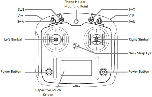
Pin Assignment Marking
The Pin 1 of each connector is
designated by square pad mark
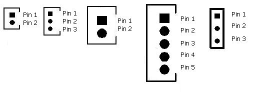
TTK60 Connector and Pin
Assignment
|
Connector
|
Description
|
Main Gun Recoil Mode
is set to AirSoft or HL Recoil Mode |
Main Gun Recoil Mode
is set to TAMIYA Recoil Mode |
|
SW |
Switch Cable Port |
HL tank already have power switch on battery cable path, so
additional switch is no longer required, just to short
pins in this port by jumper or connect to a switch cable and keep it switched
on. |
|
CH1
(2/x)
|
TK-LINK RX
|
1. Battery - (Black Wire),
connect to
Battery -
on TCK board
2.
N/C
3.
TK-LINK RX (White wire) ,
connect to the TK-LINK TX pin on TCK board |
|
CH2
(1/1)
|
TK-LINK TX
|
1. Battery - (Black Wire),
connect to
Battery -
on TCK board
2.
N/C
3.
TK-LINK RX (White wire), connect
to the TK-LINK RX pin on TCK board |
|
CH3
(1/1)
|
CH3 control
signal |
N/C |
|
CH4
(3/3)
|
CH4 control
signal
|
N/C |
|
CH5
(3/3) |
CH5 control
signal |
N/C |
|
CH6
(3/2) |
CH6 control
signal |
N/C |
|
CH7
(2/2) |
CH7 control
signal |
N/C |
|
CH8
(2/2) |
CH8 control
signal |
N/C |
|
CN1
|
Battery Power
|
1. Battery +
2.
Battery -
|
|
CN2 |
Infrared Port |
1.
HBU/TBU +
2.
HBU/TBU SIG
3.
HBU/TBU -
4. TBU FLASH LED -
5. TBU FLASH LED + |
|
CN3 |
Gun
Flash Port |
1. Battery +
2.
Strobe Trigger
3.
Battery -
4. HL AirSoft/Recoil Unit Switch
5. HL AirSoft/Recoil Unit Switch |
1. Battery +
2.
Strobe Trigger
3.
Battery -
4. TAMIYA Recoil Unit Switch
5. TAMIYA Recoil Unit Switch |
|
CN4 |
Sound
Volume |
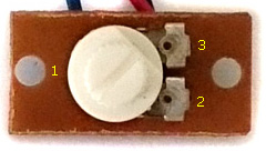
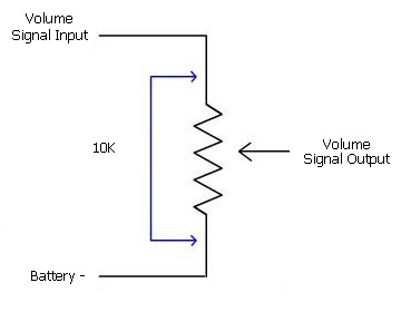
1.
Volume Signal
Output (
Wiper pin of VR
)
2. Battery -( 1 outside pin of
VR )
3.
Volume
Signal
Input (
1 outside pin of VR )
|
|
CN5 |
Speaker |
1.
Speaker -
2.
Speaker +
|
|
CN6
(2/2)
|
ESC1
|
1.
Motor +
2.
Motor -
|
|
CN6-A |
Motor Left Additional Pad
|
When 540 or 550 Motor is used
for track driving, use this pad to connect motor |
|
CN6-B |
Motor Left Additional Pad
|
When 540 or 550 Motor is used
for track driving, use this pad to connect motor |
|
CN7
(x/1)
|
ESC2 |
1.
Motor +
2.
Motor -
|
|
CN7-A |
Motor Right Additional Pad
|
When 540 or 550 Motor is used
for track driving, use this pad to connect motor |
|
CN7-B |
Motor
Right
Additional Pad
|
When 540 or 550 Motor is used
for track driving, use this pad to connect motor |
|
CN9 |
Upper
Hull Functions
(
Turn, Lift, Shoot, Light) |
1. MG LED-
2. MG2 LED-
3.
-
MG
LED+
-
MG2
LED+
-
AIRSOFT/RECOIL Motor+
4. AIRSOFT/RECOIL Motor-
5. Elevation Motor
6. Elevation Motor
7. TURRET MOTOR
8. TURRET MOTOR
*MG LED is also TK-Link RX Error indicator and turned on if not data
received.
*MG2 LED is also GBS calibration indicator and turned on during
calibration |
1.
MG LED-
2. MG2 LED-
3.
4. TAMIYA Recoil unit white Wire
5. Elevation Motor(x/x)
6. Elevation Motor(x/x)
7. TURRET MOTOR(x/3)
8. TURRET MOTOR(x/3)
*MG LED is also TK-Link RX Error indicator and turned on if not data
received.
*MG2 LED is also GBS calibration indicator and turned on during
calibration
|
|
CN10 |
NA |
N/C |
|
CN11 |
NA |
N/C |
|
CN12 |
NA
|
N/C |
|
J1 |
IR Battle Emitter
Port |
To work
with IR battle emitter(IR010)
1. IR LED +
2. IR LED - |
|
J2
(5/5) |
RealRecoilTM
Servo Port |
1. Signal( White Wire)
2.
+5V ( Red Wire)
3. Battery - (Black Wire)
See
RealRecoil section in Assembly Guide |
|
J3 |
Cannon LED Flasher Port |
1. LED +
2. LED - |
|
J4
(1/4) |
Gun Elevation Servo
Port |
1. Signal( White Wire)
2.
+5V ( Red Wire )
3. Battery - (Black Wire) |
|
J5
(3/3) |
NA
|
N/C |
|
J6 |
Programming and GBS Port |
To connect Programmer or GBS
unit |
|
J7 |
S.BUS
Port |
To connect
S.Bus Receiver
1. N/C
2.
Battery -
3.
S.BUS RX, connect to receiver S.BUS
port
4. N/C |
|
J8 |
Engine Deck Level Switch
|
1.
SWITCH
2.
SWITCH
|
|
L1 |
Rotating Light LED1
|
1. LED +
2. LED - |
|
L2 |
Rotating Light LED2
|
1. LED +
2. LED - |
|
L3 |
Rotating Light LED3
|
1. LED +
2. LED - |
|
L4 |
Controlled Switch/Tail Light |
1. Device +
2. Device -
Maximum Current : 7A
*Need
200ohm in-serial resistor when connecting LED |
|
L5 |
Aux Light 1 |
1. N/C
2. N/C |
|
L6 |
Aux
Light 2 |
1. LED +
2. LED - |
|
L7 |
GBS Indicator |
1. LED +
2. LED - |
|
L8 |
N/A |
1. N/C
2. N/C |
TCK60 Connector and Pin
Assignment
|
Connector
|
Description
|
Main Gun Recoil Mode
is set to AirSoft or HL Recoil Mode |
Main Gun Recoil Mode
is set to TAMIYA Recoil Mode |
|
SW |
Switch Cable Port |
HL tank already have power switch on battery cable path, so
additional switch is no longer required, just to short
pins in this port by jumper or connect to a switch cable and keep it switched
on. |
|
CH1
(2/x)
|
TK-LINK RX
|
1. Battery - (Black Wire),
connect to
Battery -
on TTK board
2.
N/C
3.
TK-LINK RX (White wire), connect
to the TK-LINK RX pin on TTK board |
|
CH2
(1/1)
|
TK-LINK TX
|
1. Battery - (Black Wire),
connect to
Battery -
on TTK board
2.
N/C
3.
TK-LINK TX (White wire), connect to
the TK-LINK RX pin on TTK board |
|
CH3
(1/1)
|
CH3 control
signal
|
N/A |
|
CH4
(3/3)
|
CH3 control
signal
(c7)
|
1. Battery - (Black Wire)
2.
N/C
3. Signal( White Wire) |
|
CH5
(3/3) |
CH5 control
signal |
N/A |
|
CH6
(3/2) |
CH6 control
signal |
N/A |
|
CH7
(2/2) |
CH6
(C6)
|
1. Battery - (Black Wire)
2.
N/C
3. Signal( White Wire) |
|
CH8
(2/2) |
CH8 control
signal |
N/A |
|
CN1
|
Battery Power
|
1. Battery +
2.
Battery -
|
|
CN2 |
Infrared Port |
For IR programming port
1.
HBU/TBU +
2.
HBU/TBU SIG
3.
HBU/TBU -
4. TBU FLASH LED -
5. TBU FLASH LED + |
|
CN3 |
N/A |
|
|
CN4 |
Sound
Volume |
1.
Volume Signal
Output (
Wiper pin of VR
)
2. Battery -( 1 outside pin of
VR )
3.
Volume
Signal
Input (
1 outside pin of VR )
|
|
CN5 |
Speaker |
1.
Speaker -
2.
Speaker +
|
|
CN6
|
Motor Left Track
|
|
|
CN6-A |
Motor Left Additional Pad
|
When 540 or 550 Motor is used
for track driving, use this pad to connect motor |
|
CN6-B |
Motor Left Additional Pad
|
When 540 or 550 Motor is used
for track driving, use this pad to connect motor |
|
CN7
|
Motor
Right |
|
|
CN7-A |
Motor Right Additional Pad
|
When 540 or 550 Motor is used
for track driving, use this pad to connect motor |
|
CN7-B |
Motor
Right
Additional Pad
|
When 540 or 550 Motor is used
for track driving, use this pad to connect motor |
|
CN9 |
Multi-Function
Port |
1.
MG
LED-
2. Head Light LED-
3.
MG
LED+,
Head Light LED+
4. N/C
5. ESC3 MOTOR
6. ESC3 MOTOR
7. ESC4 MOTOR
8. ESC4 MOTOR
Maximum Current for Aux Device 2 port : 7A
*Need
200ohm in-serial resistor when connecting LED
*MG LED is also TK-Link RX Error indicator and turned on if not data
received.
|
|
CN10 |
Smoke
Unit /
Smoke
Unit Fan |
1.
Smoke Unit + / Smoke Unit Fan +
2.
Smoke Unit - / Smoke Unit Fan -
|
|
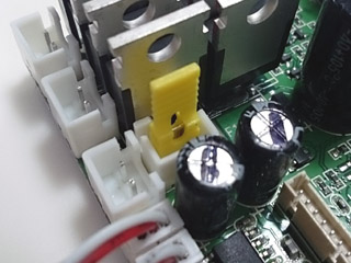
CN11 |
Smoke
Unit /
Smoke
Unit Fan switch |
1.
Switch
2.
Switch
|
|
CN12 |
Smoke
Unit
Heater
|
1.
Heater
2.
Heater
|
|
J1 |
N/A |
N/C |
|
J2 |
N/A |
N/C |
|
J3 |
Sound Pack
Processing
Indicator |
Flashing
when CPU processing sound pack
1. LED +
2. LED - |
|
J4 |
N/A |
N/C |
|
J5 |
N/A
|
N/C |
|
J6 |
Programmer Port |
To connect sound programmer |
|
J7 |
S.BUS
Port |
To connect
S.Bus Receiver
1. N/A
2.
Battery -
3.
S.BUS RX, connect to receiver S.BUS
port
4. N/A |
|
J8 |
N/A
|
N/A |
|
L1 |
AUX Light L1
|
1. LED +
2. LED - |
|
L2 |
AUX Light L2
|
1. LED +
2. LED - |
|
L3 |
AUX Light L3
|
1. LED +
2. LED - |
|
L4 |
Hull Controlled SW/Tail Light |
When
connect to a motor:
1. Motor +
2. Motor -
When connect to a
LED:
1. 200ohm in-serial resistor --> LED +
2. LED -
Maximum Current : 7A |
|
L5 |
N/A
|
1. N/C
2. N/C |
|
L6 |
AUX
Light
B |
1. LED +
2. LED -
*Can
be the position light/side mark on Leopard 2 tank |
|
L7 |
Right Blinker( Modern Tank) |
1. LED +
2. LED - |
|
L8 |
Left Blinker( Modern Tank) |
1. LED +
2. LED - |
TTK24 Connector and Pin
Assignment
|
Connector
|
Description |
Main Gun Function Mode
is configured to AirSoft or HL Recoil |
Main Gun Function Mode
is configured to TAMIYA Recoil |
|
SW |
Switch Cable
Port |
Connect to a switch cable
and keep it switched on.
|
|
CN1 |
Battery
Power |
1. Battery +
2.
Battery - |
|
CN2 |
Infrared Port |
1.
HBU/TBU +
2.
HBU/TBU SIG
3.
HBU/TBU -
4. TBU FLASH LED -
5. TBU FLASH LED + |
|
CN3
(1/x) |
Gun Flash
Port |
1. Battery +
2.
Strobe Trigger
3.
Battery -
4. AirSoft/Recoil Switch
5. AirSoft/Recoil Switch
|
1. Battery +
2.
Strobe Trigger
3.
Battery -
4. TAMIYA Recoil Unit Switch
5. TAMIYA Recoil Unit Switch |
|
CN4 |
Sound Volume |
1.
Volume Signal
Output (
Wiper pin of VR
)
2. Battery -( 1 outside
pin of VR )
3.
Volume
Signal
Input (
1 outside pin of VR )
|
|
CN5 |
Speaker |
1.
Speaker -
2.
Speaker + |
|
CN6
(x/1) |
ESC1 |
1.
Motor +
2.
Motor - |
|
CN7
(2/2) |
ESC2 |
1.
Motor +
2.
Motor - |
|
CH1 |
S.BUS port |
1. Signal
2.
+5V
3. Battery - |
|
CH2
|
TK-LINK RX
|
1. Battery - (Black Wire),
connect to
Battery -
on TCK board
2.
N/C
3.
TK-LINK RX (White wire), connect
to the TK-LINK TX pin on TCK board |
|
CH3
(2/2) |
Gun Elevation
Servo
Signal Port
|
1. Battery -, connect to servo black/brown Wire
2.
N/C
3. Signal, connect to servo white/yellow wire |
|
CH4 |
Engine Deck Level Switch Port
|
1.
SWITCH
2.
SWITCH
3.
NO CONNECTION.
* To
close Pin1 and Pin2 when gun barrel travels above engine deck |
|
CN9 |
Upper Hull Functions
( Turn, Lift, Shoot,
Light) |
1. MG LED-
2. MG2 LED-
3.
-
MG
LED+
-
MG2
LED+
-
AIRSOFT/RECOIL Motor+
4. AIRSOFT/RECOIL Motor-
5. Elevation Motor
6. Elevation Motor
7. TURRET MOTOR(1/3)
8. TURRET MOTOR(1/3)
*MG LED is also TK-Link RX Error indicator and turned on if not data
received.
*MG2 LED is also GBS calibration indicator and turned on during
calibration |
1.
MG LED-
2. MG2 LED-
3.
4. TAMIYA Recoil unit white Wire
5. Elevation Motor
6. Elevation Motor
7. TURRET MOTOR(1/3)
8. TURRET MOTOR(1/3)
*MG LED is also TK-Link RX Error indicator and turned on if not data
received.
*MG2 LED is also GBS calibration indicator and turned on during
calibration
|
|
CN10
(3/x) |
N/A |
N/A |
|
CN11 |
N/A |
N/A |
|
J1 |
IR Battle Emitter
Port |
To work with IR battle
emitter(IR010)
1. IR LED +
2. IR LED - |
|
J2
(5/5) |
RealRecoil Servo Port |
RealRecoil Servo Port is always
turned ON, no setting is needed to turn it on
1. Signal( White Wire)
2.
+5V ( Red Wire)
3. Battery - (Black Wire)
See RealRecoil section in
Assembly Guide |
|
J3 |
LED Main Gun Flasher Port |
1.
Main Gun
LED +
2.
Main Gun
LED - |
|
J4
(1/4) |
Gun Elevation
Servo
Power Port
|
1. Battery -, connect to servo black/brown Wire
2.
+5V,
connect to servo red wire
3.
N/C |
|
J5
(3/3) |
TK-LINK TX
|
1. Battery - (Black Wire),
connect to
Battery -
on TCK board
2.
N/C
3.
TK-LINK TX (White wire), connect
to the TK-LINK RX pin on TCK board |
|
J6 |
Programming and GBS unit Port |
To connect TK Programmer or
GBS unit
|
TCK24/TCK40 Connector and Pin
Assignment
|
Connector
|
Description
|
Pin assignments |
|
SW |
Switch Cable Port |
HL tank already have power switch on battery cable path, so
additional switch is no longer required, just to short
pins in this port by jumper or connect to a switch cable and keep it switched
on.
|
|
CN1 |
Battery Power
|
1. Battery +
2.
Battery -
|
|
CN2 |
Infrared Port |
1.
HBU/TBU +
2.
HBU/TBU SIG
3.
HBU/TBU -
4. TBU FLASH LED -
5. TBU FLASH LED + |
|
CN3
(1/x) |
N/A |
1.
N/C
2.
N/C
3.
N/C
4. N/C
5. N/C |
|
CN4 |
Sound
Volume |
1.
Volume Signal
Output (
Wiper pin of VR
)
2. Battery -( 1 outside pin of
VR )
3.
Volume
Signal
Input (
1 outside pin of VR ) |
|
CN5 |
Speaker |
1.
Speaker -
2.
Speaker +
|
|
CN6
(x/1) |
Motor Left
|
|
|
CN7
(2/2) |
Motor
Right |
|
|
CH1 |
S.BUS Port |
1. Signal
2.
+5V
3. Battery - |
|
CH2
|
TK-LINK RX
|
1. Battery - (Black Wire),
connect to
Battery -
on TTK board
2.
N/C
3.
TK-LINK RX (White wire), connect
to the TK-LINK TX pin on TTK board |
|
CH3 |
TK-LINK TX
|
1. Battery - (Black Wire),
connect to
Battery -
on TTK board
2.
N/C
3.
TK-LINK TX (White wire), connect
to the TK-LINK RX pin on TTK board |
|
CH4 |
NA
|
1. N/C
2. N/C
3.
N/C |
|
CN9 |
Upper
Hull Functions
(
Turn, Lift, Shoot, Light) |
1.
MG
LED-
2. Head Light LED-
3.
-
MG
LED+
-
Head Light LED+
-
Controlled Switch
+
4.
Controlled Switch -
5. ESC3 MOTOR
6. ESC3 MOTOR
7. ESC4 MOTOR
8. ESC4 MOTOR
*Maximum Current for
controlled Switch
port : 7A
*Need
200ohm in-serial resistor when connecting LED
*MG LED is also TK-Link RX Error indicator and turned on if not data
received. |
|
CN10
(3/x) |
Smoke
Unit |
1.
Smoke Unit
2.
Smoke Unit |
|
CN11 |
Smoke
Unit Switch |
1.
Switch
2.
Switch |
|
J1 |
IR Battle Emitter
Port |
To work with IR battle
emitter(IR010)
1. IR LED +
2. IR LED - |
|
J2
(5/5) |
IR programming mode detection |
1.
Signal
2. 5V
3.
Battery
|
|
J3 |
HeaSound Pack
Processing
Indicator |
Flashing
when CPU processing sound pack
1. LED +
2. LED - |
|
J4
(1/4) |
Left Blinker
|
Connect to a
LED:
1. N.C.
2. --->200ohm in-serial resistor --> LED +
3.
LED - |
|
J5
(3/3) |
Right Blinker
|
Connect to a
LED:
1. N.C.
2. --->200ohm in-serial resistor --> LED +
3.
LED - |
|
J6 |
Sound Programming Port |
To connect TK Programmer
|
TTK50SP/SPG Connector
and Pin Assignment
TTK50
EPM Setting and limitation
|
EPM No., Application |
ESC
mode
ESC/Ultrasonic ESC port |
PWM mode
PWM port |
|
EPM1
For Gun Elevation |
CN9.5
CN9.6 |
J4* |
|
EPM2
For Turret
rotation
|
CN7*
|
CH4
(Only available in
None GBS version )
|
|
EPM3,
For
RWS rotation |
CN6* |
N/A |
|
EPM4,
For
RWS elevation
|
CN9.7
CN9.8
|
J5*
|
*Default setting
RWS (
TTK.EMP3,TTK. EPM4 and TTK.MG2 ) control ownership
|
|
TTK.SwA Up |
TTK.SwA Down
( Co. Override state) |
|
TCK.SwA Up
(Driver On state) |
TCK owns
TTK.EPM3
TTK.EPM4
TTK.MG2
|
TTK owns
-
TTK.EPM3,
-
TTK.EPM4
-
TTK.MG2
|
|
TCK.SwA Down
(Driver Off state) |
N/A |
TTK owns
-
TTK.EPM3,
-
TTK.EPM4
-
TTK.MG2
|
|
Connector
|
Description |
Main Gun Function Mode
is configured to AirSoft or HL Recoil |
Main Gun Function Mode
is configured to TAMIYA Recoil |
|
SW |
Switch Cable
Port |
Connect to a switch cable
and keep it switched on.
|
|
CN1 |
Battery
Power |
1. Battery +
2.
Battery - |
|
CN2 |
Infrared Port |
1.
HBU/TBU +
2.
HBU/TBU SIG
3.
HBU/TBU -
4. TBU FLASH LED -
5. TBU FLASH LED + |
|
CN3 |
Gun Flash
Port |
1. Battery +
2.
Strobe Trigger
3.
Battery -
4. AirSoft/Recoil Switch
5. AirSoft/Recoil Switch
|
1. Battery +
2.
Strobe Trigger
3.
Battery -
4. TAMIYA Recoil Unit Switch
5. TAMIYA Recoil Unit Switch |
|
CN4 |
Sound Volume |
1.
Volume Signal
Output (
Wiper pin of VR
)
2. Battery -( 1 outside
pin of VR )
3.
Volume
Signal
Input (
1 outside pin of VR )
|
|
CN5 |
Speaker |
1.
Speaker -
2.
Speaker + |
|
CN6 |
EPM3. ESC |
1.
Motor +
2.
Motor -
*Please refer to TTK50 EPM
Setting Table |
|
CN7 |
EPM4.ESC
(Turret) |
1.
Motor +
2.
Motor -
*Please refer to TTK50 EPM
Setting Table |
|
CH1 |
S.BUS port |
1. Signal
2.
+5V
3. Battery - |
|
CH2
|
TK-LINK RX
|
1. Battery - (Black Wire),
connect to
Battery -
on TCK board
2.
N/C
3.
TK-LINK RX (White wire), connect
to the TK-LINK TX pin on TCK board |
|
CH3 |
TK-LINK TX |
1. Battery - (Black Wire),
connect to
Battery -
on TTK board
2.
N/C
3.
TK-LINK TX (White wire), connect
to the TK-LINK RX pin
on TTK board |
|
CH4 |
EPM2.PWM
/
Engine Deck Level Switch Port
|
TTK50SP:
EPM2.PWM
1. Battery -(Black Wire)
2.
+5V( Red Wire)
3. Signal( White Wire)
TTK50SPG:
Engine Deck Level Switch Port
1.
NO CONNECTION.
2.
SWITCH
3.
SWITCH
* To
close Pin1 and Pin2 when gun barrel travels above engine deck
*Only
|
|
CN9 |
Upper Hull Functions
( Turn, Lift, Shoot,
Light) |
1. MG LED-
2. MG2 LED-
3.
-
MG
LED+
-
MG2
LED+
-
AIRSOFT/RECOIL Motor+
4. AIRSOFT/RECOIL Motor-
5. Elevation Motor
6. Elevation Motor
7. (TTK.EPM2.ESC)
8. (TTK.EPM2.ESC)
*MG LED is also TK-Link RX Error indicator and turned on if not data
received.
*MG2 LED is also GBS calibration indicator and turned on during
calibration |
1.
MG LED-
2. MG2 LED-
3.
4. TAMIYA Recoil unit white Wire
5. Elevation Motor
6. Elevation Motor
7. (TTK.EPM2.ESC)
8. (TTK.EPM2.ESC)
*MG LED is also TK-Link RX Error indicator and turned on if not data
received.
*MG2 LED is also GBS calibration indicator and turned on during
calibration
|
|
CN10
(3/x) |
Aux Light 2 |
Pin 1 is
connected to Battery + when turned on
Pin 2 is
always Battery -
When connect to LED
1
--> 200 ohm resistor --> LED+
2. LED-
When connect to
Rotating Light Module
1.
-->
5V regulator -->
Rotating Light Module port +
2.
Rotating Light Module port -
When connect to
Cannon smoke heater
1.
Cannon
smoke heater pin 1
2.
Cannon
smoke heater pin 2
|
|
CN11 |
Aux Light 2
Switch |
1.
SWITCH
2.
SWITCH
switch on to enable
CN10 port, off to disable CN10
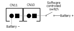
Equivalent circuit of CN10 and CN11
|
|
J1 |
IR Battle Emitter
Port |
To work with IR battle
emitter(IR010)
1. IR LED +
2. IR LED - |
|
J2
(5/5) |
RealRecoil Servo Port |
RealRecoil Servo Port is always
turned ON, no setting is needed to turn it on
1. Battery - (Black Wire)
2.
+5V ( Red Wire)
3. Signal( White Wire)
See RealRecoil section in
Assembly Guide |
|
J3 |
LED Main Gun Flasher Port |
1.
Main Gun
LED +
2.
Main Gun
LED - |
|
J4 |
EPM1.PWM
|
Gun Elevation Servo Port
1. Battery -, connect to servo black/brown Wire
2.
+5V,
connect to servo red wire
3.
Signal |
|
J5 |
EPM2.PWM |
1. Battery -,
connect to servo black/brown Wire
2.
+5V
3. Signal |
|
J6 |
Programming and GBS unit Port |
To connect TK Programmer or
GBS unit
|
V2.2
|
Connector
|
Description |
Upper
Hull Functions (CN9)
Mode
|
|
Airsoft
|
Tamiya Recoil |
Cannon
Smoke |
|
SW |
Switch Cable
Port |
HL tank
already have power switch on battery cable path, so additional
switch is no longer required, just to short
pins in this port by jumper
or connect to a switch cable and keep it switched on.
|
|
CN1 |
Battery
Power |
1. Battery +
2.
Battery - |
|
CN2 |
Infrared Port |
1.
HBU/TBU +
2.
HBU/TBU SIG
3.
HBU/TBU -
4. TBU FLASH LED -
5. TBU FLASH LED + |
|
CN3 |
Gun Flash
Port |
1. Battery +
2.
Strobe Trigger
3.
Battery -
4. AirSoft/Recoil Switch
5. AirSoft/Recoil Switch
|
1. Battery +
2.
Strobe Trigger
3.
Battery -
4. TAMIYA Recoil Unit Switch
5. TAMIYA Recoil Unit Switch |
1. Battery +
2.
Strobe Trigger
3.
Battery -
4. NC
5. NC |
|
CN4 |
Sound Volume |
1.
Volume Signal
Output (
Wiper pin of VR
)
2. Battery -( 1 outside
pin of VR )
3.
Volume
Signal
Input (
1 outside pin of VR )
|
|
CN5 |
Speaker |
1.
Speaker -
2.
Speaker + |
|
CN6
(*x/1) |
EPM3. ESC |
1.
Motor +
2.
Motor -
*Please refer to TTK50 EPM
Setting Table |
|
CN7
(*2/2) |
EPM4.ESC
(Turret) |
1.
Motor +
2.
Motor -
*Please refer to TTK50 EPM
Setting Table |
|
CH1 |
S.BUS port
|
1. Signal
2.
+5V
3. Battery - |
|
CH2 |
TK-LINK RX
|
1. Battery - (Black Wire),
connect to
Battery -
on TCK board
2.
N/C
3.
TK-LINK RX (White wire), connect
to the TK-LINK TX pin on TCK board |
|
CH3
(*2/0) |
TK-LINK TX |
1. Battery - (Black Wire),
connect to
Battery -
on TTK board
2.
N/C
3.
TK-LINK TX (White wire), connect
to the TK-LINK RX pin
on TTK board |
|
CH4 |
EPM2.PWM
/
Engine Deck Level Switch Port
|
TTK50SP:
EPM2.PWM
1. Battery -(Black Wire)
2.
+5V( Red Wire)
3. Signal( White Wire)
TTK50SPG:
Engine Deck Level Switch Port
1.
NO CONNECTION.
2.
SWITCH
3.
SWITCH
* To
close Pin1 and Pin2 when gun barrel travels above engine deck
*Only
|
|
CN9 |
Upper Hull Functions
( Turn, Lift, Shoot,
Light) |
1. MG1 LED-
2. Head Light LED-
3. MG1 LED+,
Head Light LED+ &
AIRSOFT
Motor+
4. AIRSOFT Motor-
5. GUN ELEVATE MOTOR (*0/3)
6. GUN ELEVATE MOTOR
7. TURRET MOTOR (*0/4)
8. TURRET MOTOR(*0/4) |
1. MG1 LED-
2. Head Light LED-
3. MG1 LED+,
Head Light LED+ &
TAMIYA
Recoil unit
green Wire
4. TAMIYA Recoil unit white Wire
5. GUN ELEVATE MOTOR(*0/3)
6. GUN ELEVATE MOTOR(*0/3)
7. TURRET MOTOR(*0/4)
8. TURRET MOTOR(*0/4) |
1. MG1 LED-
2. Head Light LED-
3. MG1 LED+,
Head Light LED+ &
Air Pump +
4. Air Pump-
5. GUN ELEVATE MOTOR(*0/3)
6. GUN ELEVATE MOTOR(*0/3)
7. TURRET MOTOR(*0/4)
8. TURRET MOTOR(*0/4) |
|
CN10
(*3/0) |
Aux Light 2 |
Pin 1 is
connected to Battery + when turned on
Pin 2 is
always Battery -
When connect to LED
1
--> 200 ohm resistor --> LED+
2. LED-
When connect to
Rotating Light Module
1.
-->
5V regulator -->
Rotating Light Module port +
2.
Rotating Light Module port -
When connect to
Cannon smoke heater
1.
Cannon smoke heater pin 1
2.
Cannon smoke heater pin 2 |
|
CN11 |
Aux Light 2
Switch |
1.
SWITCH
2.
SWITCH
switch on to enable
CN10 port, off to disable CN10
Equivalent circuit of CN10 and CN11
|
|
J1 |
IR Battle Emitter
Port |
To work with IR battle
emitter(IR010)
1. IR LED +
2. IR LED - |
|
J2
(*5) |
RealRecoil Servo Port |
RealRecoil Servo Port is always
turned ON, no setting is needed to turn it on
1. Signal( White Wire)
2.
+5V ( Red Wire)
3. Battery - (Black Wire)
See RealRecoil section in
Assembly Guide |
|
J3 |
LED Main Gun Flasher Port |
1.
Main Gun
LED +
2.
Main Gun
LED - |
|
J4
(*1/5) |
EPM1.PWM
|
1. Battery -,
connect to servo black/brown Wire
2.
+5V
3. Signal |
|
J5
(*3/3) |
EPM2.PWM |
1. Battery -,
connect to servo black/brown Wire
2.
+5V
3. Signal |
|
J6 |
Programming and GBS unit Port |
To connect TK Programmer or
GBS unit
|
TCK50SP Connector and Pin
Assignment
|
Connector
|
Description
|
Pin assignments |
|
SW |
Switch Cable Port |
HL tank already have power switch on battery cable path, so
additional switch is no longer required, just to short
pins in this port by jumper or connect to a switch cable and keep it switched
on.
|
|
CN1 |
Battery Power
|
1. Battery +
2.
Battery -
|
|
CN2 |
Infrared Port |
1.
N/C
2.
N/C
3.
N/C
4. N/C
5. N/C |
|
CN3
(1/x) |
NC |
1.
N/C
2.
N/C
3.
N/C
4. N/C
5. N/C |
|
CN4 |
Sound
Volume |
1.
Volume Signal
Output (
Wiper pin of VR
)
2. Battery -( 1 outside pin of
VR )
3.
Volume
Signal
Input (
1 outside pin of VR ) |
|
CN5 |
Speaker |
1.
Speaker -
2.
Speaker +
|
|
CN6
(x/1) |
Motor Left
|
|
|
CN7
(2/2) |
Motor
Right |
|
|
CH1 |
S.BUS Port |
1. Signal
2.
+5V
3. Battery - |
|
CH2
|
TK-LINK RX
|
1. Battery - (Black Wire),
connect to
Battery -
on TTK board
2.
N/C
3.
TK-LINK RX (White wire), connect
to the TK-LINK TX pin on TTK board |
|
CH3 |
TK-LINK TX
|
1. Battery - (Black Wire),
connect to
Battery -
on TTK board
2.
N/C
3.
TK-LINK RX (White wire), connect
to the TK-LINK RX pin on TTK board |
|
CH4 |
Hull mount MG |
Connect to a
LED:
1. N/C
2. LED +
3.
LED -
*Hull
mount MG
LED is also TK-Link RX Error indicator and turned on if not data received.
*
Hull mount MG
LED也是TK資料鍊接收錯誤指示燈,
當沒接收到信號或錯誤信號時會亮起
|
|
CN9 |
Upper
Hull Functions
(
Turn, Lift, Shoot, Light) |
1. Left Blinker
LED-
2. Right Blinker LED-
3.
-
Left Blinker
LED+
-
Right Blinker LED+
-
Smoke Heater +
4. Smoke Heater
-
5. TCK.EPM1.ESC
6. TCK.EPM1.ESC
7. TCK.EPM2.ESC
8. TCK.EPM2.ESC
*Maximum Current on Hull
controlled Switch
port : 7A
*Need
200ohm in-serial resistor when connecting LED
*Hull
controlled Switch
port
can be used for Smoker Heater and turn it on when needed. |
|
CN10
(3/x) |
Smoke
Unit |
1.
Smoke Unit/ Smoke Fan
2.
Smoke Unit/ Smoke Fan |
|
CN11 |
Smoke
Unit Switch |
1.
Smoke Unit/ Smoke Fan Switch
2.
Smoke Unit/ Smoke Fan Switch |
|
J1 |
IR Battle Emitter
Port |
To work with IR battle
emitter(IR010)
1. IR LED +
2. IR LED - |
|
J2
(5/5) |
IR programming mode detection |
1. Battery - (Black Wire)
2.
+5V ( Red Wire)
3. Signal( White Wire) |
|
J3 |
Head Light/
Sound Pack Processing
Indicator |
Head Light/Flashing
when CPU processing sound pack
1. LED +
2. LED - |
|
J4
(1/4) |
TCK.EPM1.PWM
|
1. Battery - (Black Wire)
2.
+5V ( Red Wire)
3. Signal( White Wire) |
|
J5
(3/3) |
TCK.EPM2.PWM
|
1. Battery - (Black Wire)
2.
+5V ( Red Wire)
3. Signal( White Wire) |
|
J6 |
Sound Programming Port |
To connect TK Programmer
|
TTK39SP/G Connector and Pin
Assignment
V1 Release
|
Connector
|
Description
|
Main Gun Function Mode
is configured to AirSoft or HL Recoil |
Main Gun Function Mode
is configured to TAMIYA Recoil |
|
SW |
Switch Cable Port |
Connect to a switch |
|
CN1
|
Battery Power
|
1. Battery +
2.
Battery -
|
|
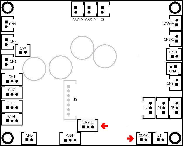
CN2-1 |
IR Battle Receiver Port
紅外對戰接收器 |
1.
HBU/TBU -
2.
HBU/TBU SIG
3.
HBU/TBU +
|
|
CN2-2 |
IR battle indicator
Port
紅外對戰指示燈 |
1. TBU FLASH LED +
2. TBU FLASH LED - |
|
CN3
(1/x) |
Sync Switch Port
同步開關 |
1. AirSoft/Recoil Switch
2. AirSoft/Recoil Switch
|
1. TAMIYA Recoil Unit Switch
2. TAMIYA Recoil Unit Switch |
|
CN4 |
Sound
Volume
音量控制 |
1.
Volume Signal
Output (
Wiper pin of VR
)
2. Battery -( 1 outside pin of
VR )
3.
Volume
Signal
Input (
1 outside pin of VR )
|
|
CN5 |
Speaker
喇叭 |
1.
Speaker -
2.
Speaker +
|
|
CN6
(x/1)
|
ESC1
|
1.
Motor
2.
Motor
|
|
CN7
(2/2)
|
ESC2 |
1.
Motor
2.
Motor
|
|
CH1 |
S.BUS |
1. Battery -
2.
+5V
3. Signal |
|
FPV RX Port |
1. Battery -
2.
+5V
3.
FPV RX |
|
CH2
|
Engine Deck Level Switch Port
引擎室迴避開關
|
If not set to FPV TX: act as Engine Deck
Level Switch Port
1.
NO CONNECTION.
2.
SWITCH
3.
SWITCH
* To close Pin2 and Pin3 when gun barrel travels
above engine deck |
|
FPV TX |
If set to FPV TX pin: act as FPV TX
1. Battery -
2.
+5V
3. FPV TX |
|
CH3 |
TK-LINK RX
TK資料鍊
接收 |
1. Battery - (Black Wire),
connect to
Battery -
on TCK board
2.
N/C
3.
TK-LINK RX (White wire), connect to
the TK-LINK TX pin on TCK board |
|
CH4 |
TK-LINK TX
TK資料鍊
傳送
|
1. Battery - (Black Wire),
connect to
Battery -
on TCK board
2.
N/C
3.
TK-LINK TX (White wire), connect to
the TK-LINK TX pin on TCK board |
|
CN9-1 |
MG LED
機槍燈光 |
1.
MG
LED+
2.
MG
LED-
*MG LED is also TK-Link RX Error indicator and turned on if not data
received.
*
MG LED也是TK資料鍊接收錯誤指示燈,
當沒接收到信號或錯誤信號時會亮起 |
|
CN9-2 |
MG2 LED
機槍2燈光 |
1.
MG2 LED+
2.
MG2 LED-
*MG2 LED is also GBS calibration indicator and turned on during
calibration
*
MG2 LED也是GBS校正指示燈,
當開機校正時會亮起
|
|
CN9-3 |
AirSoft/Recoil Motor
空氣槍/砲縮馬達 |
1.AIRSOFT/RECOIL Motor+
2.AIRSOFT/RECOIL Motor-
|
1. TAMIYA
Recoil unit
green Wire
2. TAMIYA Recoil unit white Wire
|
|
CN9-4
(x/4) |
GUN ELEVATE Motor
主砲俯仰馬達 |
1. GUN ELEVATE MOTOR+
2. GUN ELEVATE MOTOR-
|
|
CN9-5
(1/3) |
TURRET MOTOR
砲塔迴轉馬達 |
7. TURRET MOTOR+
8. TURRET MOTOR- |
|
CN10
(3/x) |
N/C
*Ver.1 |
1.N/C
2.N/C |
|
CN10
(3/x) |
Aux Light 1
*Ver 2. 20200321 |
Pin 1 is
connected to Battery + when turned on
Pin 2 is
always Battery -
If connect to LED
1
--> 200 ohm resistor --> LED+
2. LED-
If connect to
Rotating Light Module
1.
-->
5V regulator -->
Rotating Light Module port +
2.
Rotating Light Module port -
|
|
J1 |
IR Battle Emitter
Port
紅外對戰發射器 |
To work
with IR battle emitter(IR010)
1. IR LED +
2. IR LED - |
|
J2
(5/5) |
RealRecoil Servo Port
砲縮伺服機 |
1. Battery - (Black Wire)
2.
+5V ( Red Wire)
3. Signal( White Wire) |
|
J3 |
Main Gun LED
Flasher Port
主炮LED |
1.
Main Gun
LED +
2.
Main Gun
LED - |
|
J4
(1/4) |
Gun Elevation Servo Port
主砲俯仰伺服機
|
1. Battery - (Black Wire)
2.
+5V ( Red Wire )
3. Signal( White Wire) |
|
J5
(3/3) |
Turret
Rotate/Gun Traverse Servo Port砲塔迴轉馬達 |
1. Battery - (Black Wire)
2.
+5V ( Red Wire )
3. Signal( White Wire) |
|
J6 |
Programming and GBS unit Port
燒錄音效及砲穩功能感測器 |
To connect TK Programmer or
GBS unit
|
TTK39SP/SPG V2 EPM
Setting and limitation
|
EPM No., Application |
ESC
mode
ESC/Ultrasonic ESC port |
PWM mode
PWM port |
|
EPM1
For Gun Elevation |
CN9.5
CN9.6 |
J4 |
|
EPM2
For Turret
rotation
|
CN7
|
CH4
(Only available in None GBS version )
|
|
EPM3,
For
RWS rotation |
CN6 |
N/A |
|
EPM4,
For
RWS elevation
|
CN9.7
CN9.8
|
J5
|
|
Connector
|
Description
|
Main Gun Function Mode
is configured to AirSoft or HL Recoil |
Main Gun Function Mode
is configured to TAMIYA Recoil |
|
SW |
Switch Cable Port |
Connect to a switch |
|
CN1
|
Battery Power
|
1. Battery +
2.
Battery -
|
|
CN2-1 |
IR Battle Receiver Port
紅外對戰接收器 |
1.
HBU/TBU -
2.
HBU/TBU SIG
3.
HBU/TBU +
|
|
CN2-2 |
IR battle indicator
Port
紅外對戰指示燈 |
1. TBU FLASH LED +
2. TBU FLASH LED - |
|
CN3
(1/x) |
Sync Switch Port
同步開關 |
1. AirSoft/Recoil Switch
2. AirSoft/Recoil Switch
|
1. TAMIYA Recoil Unit Switch
2. TAMIYA Recoil Unit Switch |
|
CN4 |
Sound
Volume
音量控制 |
1.
Volume Signal
Output (
Wiper pin of VR
)
2. Battery -( 1 outside pin of
VR )
3.
Volume
Signal
Input (
1 outside pin of VR )
|
|
CN5 |
Speaker
喇叭 |
1.
Speaker -
2.
Speaker +
|
|
CN6
(x/1)
|
ESC1
|
1.
Motor
2.
Motor
|
|
CN7
(2/2)
|
ESC2 |
1.
Motor
2.
Motor
|
|
CH1 |
S.BUS port |
1. Signal
2.
+5V
3. Battery - |
|
CH2
|
TK-LINK RX
|
1. Battery - (Black Wire),
connect to
Battery -
on TCK board
2.
N/C
3.
TK-LINK RX (White wire), connect
to the TK-LINK TX pin on TCK board |
|
CH3 |
TK-LINK TX |
1. Battery - (Black Wire),
connect to
Battery -
on TTK board
2.
N/C
3.
TK-LINK RX (White wire), connect
to the TK-LINK RX pin
on TTK board |
|
CH4 |
EPM2.PWM
/
Engine Deck Level Switch Port
|
TTK39SP:
EPM2.PWM
1. Battery -(Black Wire)
2.
+5V( Red Wire)
3. Signal( White Wire)
TTK39SPG:
Engine Deck Level Switch Port
1.
SWITCH
2.
SWITCH
3.
NO CONNECTION.
* To
close Pin1 and Pin2 when gun barrel travels above engine deck
*Only
|
|
CN9-1 |
MG LED
機槍燈光 |
1.
MG
LED+
2.
MG
LED-
*MG LED is also TK-Link RX Error indicator and turned on if not data
received.
*
MG LED也是TK資料鍊接收錯誤指示燈,
當沒接收到信號或錯誤信號時會亮起 |
|
CN9-2 |
MG2 LED
機槍2燈光 |
1.
MG2 LED+
2.
MG2 LED-
*MG2 LED is also GBS calibration indicator and turned on during
calibration
*
MG2 LED也是GBS校正指示燈,
當開機校正時會亮起
|
|
CN9-3 |
AirSoft/Recoil Motor
空氣槍/砲縮馬達 |
1.AIRSOFT/RECOIL Motor+
2.AIRSOFT/RECOIL Motor-
|
1. TAMIYA
Recoil unit
green Wire
2. TAMIYA Recoil unit white Wire
|
|
CN9-4
(x/4) |
GUN ELEVATE Motor
主砲俯仰馬達 |
1. GUN ELEVATE MOTOR+
2. GUN ELEVATE MOTOR-
|
|
CN9-5
(1/3) |
TURRET MOTOR
砲塔迴轉馬達 |
7. TURRET MOTOR+
8. TURRET MOTOR- |
|
CN10
(3/x) |
N/C
*Ver.1 |
1.N/C
2.N/C |
|
CN10
(3/x) |
Aux Light 1
*Ver 2. 20200321 |
Pin 1 is
connected to Battery + when turned on
Pin 2 is
always Battery -
If connect to LED
1
--> 200 ohm resistor --> LED+
2. LED-
If connect to
Rotating Light Module
1.
-->
5V regulator -->
Rotating Light Module port +
2.
Rotating Light Module port -
|
|
J1 |
IR Battle Emitter
Port
紅外對戰發射器 |
To work
with IR battle emitter(IR010)
1. IR LED +
2. IR LED - |
|
J2
(5/5) |
RealRecoil Servo Port
砲縮伺服機 |
1. Battery - (Black Wire)
2.
+5V ( Red Wire)
3. Signal( White Wire) |
|
J3 |
Main Gun LED
Flasher Port
主炮LED |
1.
Main Gun
LED +
2.
Main Gun
LED - |
|
J4
(1/4) |
Gun Elevation Servo Port
主砲俯仰伺服機
|
1. Battery - (Black Wire)
2.
+5V ( Red Wire )
3. Signal( White Wire) |
|
J5
(3/3) |
Turret
Rotate/Gun Traverse Servo Port砲塔迴轉馬達 |
1. Battery - (Black Wire)
2.
+5V ( Red Wire )
3. Signal( White Wire) |
|
J6 |
Programming and GBS unit Port
燒錄音效及砲穩功能感測器 |
To connect TK Programmer or
GBS unit
|
TCK39 Connector and Pin
Assignment
|
Connector
|
Description
|
Main Gun Function Mode
is configured to AirSoft or HL Recoil |
Main Gun Function Mode
is configured to TAMIYA Recoil |
|
SW |
Switch Cable Port |
Connect to a switch |
|
CN1
|
Battery Power
|
1. Battery +
2.
Battery -
|
|
CN2-1 |
Infrared RX Port |
1.
HBU/TBU -
2.
HBU/TBU SIG
3.
HBU/TBU +
|
|
CN2-2 |
Infrared LED Port |
1. TBU FLASH LED +
2. TBU FLASH LED - |
|
CN3 |
Sync Switch Port |
1. AirSoft/Recoil Switch
2. AirSoft/Recoil Switch
|
1. TAMIYA Recoil Unit Switch
2. TAMIYA Recoil Unit Switch |
|
CN4 |
Sound
Volume |
1.
Volume Signal
Output (
Wiper pin of VR
)
2. Battery -( 1 outside pin of
VR )
3.
Volume
Signal
Input (
1 outside pin of VR )
|
|
CN5 |
Speaker |
1.
Speaker -
2.
Speaker +
|
|
CN6
(x/1)
|
Motor Left
|
1.
Motor
2.
Motor
|
|
CN7
(2/2)
|
Motor
Right |
1.
Motor
2.
Motor
|
|
CH1 |
S.BUS Port |
1. Battery -
2.
+5V
3. Signal |
|
CH2
|
TK-LINK RX
|
1. Battery - (Black Wire),
connect to
Battery -
on TTK board
2.
N/C
3.
TK-LINK RX (White wire), connect to
the TK-LINK TX pin on TTK board |
|
CH3 |
TK-LINK TX |
1. Battery - (Black Wire),
connect to
Battery -
on TTK board
2.
N/C
3.
TK-LINK TX (White wire), connect to
the TK-LINK RX pin on TTK board |
|
CH4 |
N/A
|
1.
NO CONNECTION.
2.
SWITCH
3.
SWITCH
* To
close Pin1 and Pin2 when gun barrel travels above engine deck |
|
CN9-1 |
MG LED |
1.
MG
LED+
2.
MG
LED-
*MG LED is also TK-Link RX Error indicator and turned on if not data
received. |
|
CN9-2 |
MG2 LED |
1.
MG2 LED+
2.
MG2 LED-
*MG2 LED is also GBS calibration indicator and turned on during
calibration
|
|
CN9-3 |
Upper
Hull Functions
3 |
1.AIRSOFT/RECOIL Motor+
2.AIRSOFT/RECOIL Motor-
|
1. TAMIYA
Recoil unit
green Wire
2. TAMIYA Recoil unit white Wire
|
|
CN9-4
(x/4) |
Upper
Hull Functions
4 |
1. GUN ELEVATE MOTOR+
2. GUN ELEVATE MOTOR-
|
|
CN9-5
(1/3) |
Upper
Hull Functions
5 |
7. TURRET MOTOR+
8. TURRET MOTOR- |
|
CN10
(3/x) |
Smoker |
1. Smoke unit +
2. Smoke unit - |
|
J1 |
IR Battle Emitter
Port |
To work
with IR battle emitter(IR010)
1. IR LED +
2. IR LED - |
|
J2
(5/5) |
IR programming mode detection |
1.
N/C
2.
+5V ( Red Wire)
3. Signal( White Wire) |
|
J3 |
Sound Pack
Processing
Indicator |
Flashing
when CPU processing sound pack
1. LED +
2. LED - |
|
J4
(1/4) |
Left Blinker
|
Connect to a
LED:
1. N/C
2. --->200ohm in-serial resistor --> LED +
3.
LED- |
|
J5
(3/3) |
Right Blinker |
Connect to a
LED:
1. N/C
2. --->200ohm in-serial resistor --> LED +
3.
LED- |
|
J6 |
Programming and GBS unit Port |
To connect TK Programmer or
GBS unit
|
GTK39 Gepard Tank Turret
Controller Connector and Pin Assignment
|
Connector
|
Description
|
Main Gun Function Mode
is configured to AirSoft or HL Recoil |
Main Gun Function Mode
is configured to TAMIYA Recoil |
|
SW |
Switch Cable Port |
Connect to a switch |
|
CN1
|
Battery Power
|
1. Battery +
2.
Battery -
|
|
CN2-1 |
Infrared RX Port |
1.
HBU/TBU -
2.
HBU/TBU SIG
3.
HBU/TBU +
|
|
CN2-2 |
Infrared LED Port |
1. TBU FLASH LED +
2. TBU FLASH LED - |
|
CN3 |
NA |
1. N/C
2. N/C |
|
CN4 |
Sound
Volume |
1.
Volume Signal
Output (
Wiper pin of VR
)
2. Battery -( 1 outside pin of
VR )
3.
Volume
Signal
Input (
1 outside pin of VR )
|
|
CN5 |
Speaker |
1.
Speaker -
2.
Speaker +
|
|
CN6
(x/1)
|
ESC1
|
1.
ESC +
2.
ESC -
|
|
CN7
(2/2)
|
ESC2 |
1.
ESC +
2.
ESC -
|
|
CH1 |
S.BUS Port |
1. Signal
2.
+5V
3. Battery - |
|
CH2
|
TK-LINK RX
|
1. Battery - (Black Wire),
connect to
Battery -
on TTK board
2.
N/C
3.
TK-LINK RX (White wire), connect to
the TK-LINK TX pin on TTK board |
|
CH3 |
TK-LINK TX |
1. Battery - (Black Wire),
connect to
Battery -
on TTK board
2.
N/C
3.
TK-LINK TX( White wire), connect to
the TK-LINK RX pin on TTK board |
|
CH4 |
Engine Deck Level Switch
Port
|
1.
SWITCH
2.
SWITCH
3.
NO CONNECTION.
* To
close Pin1 and Pin2 when gun barrel travels above engine deck |
|
CN9-1 |
35mm cannon LED 1 |
1.
MG
LED+
2.
MG
LED-
*MG LED is also TK-Link RX Error indicator and turned on if not data
received. |
|
CN9-2 |
35mm cannon LED 2 |
1.
MG2 LED+
2.
MG2 LED-
*MG2 LED is also GBS calibration indicator and turned on during
calibration
|
|
CN9-3 |
Upper
Hull Functions
3 |
1.35mm cannon recoil
Solenoid+
2.35mm
cannon recoil Solenoid-
|
|
CN9-4
(x/4) |
Upper
Hull Functions
4 |
1. GUN ELEVATE MOTOR+
2. GUN ELEVATE MOTOR-
|
|
CN9-5
(1/3) |
Upper
Hull Functions
5 |
7. TURRET MOTOR+
8. TURRET MOTOR- |
|
CN10
(3/x) |
N/A |
1. N/C
2. N/C |
|
J1 |
IR Battle Emitter
Port |
To work
with IR battle emitter(IR010)
1. IR LED +
2. IR LED - |
|
J2
(5/5) |
Searching Radar
elevation
Servo Port |
1. Battery - (Black Wire)
2.
+5V ( Red Wire)
3. Signal( White Wire) |
|
J3 |
Searching Radar
return position switch |
1. Switch
2.
Switch |
|
J4
(1/4) |
Targeting
Radar Elevation Servo
Port |
1. Battery - (Black Wire)
2.
+5V ( Red Wire)
3. Signal( White Wire) |
|
J5
(3/3) |
Targeting Radar rotating servo port |
1. Battery - (Black Wire)
2.
+5V ( Red Wire)
3. Signal( White Wire) |
|
J6 |
Programming and GBS unit Port |
To connect TK Programmer or
GBS unit
|
TTK80SPG & TCK80S Turret
Controller Connector and Pin Assignment
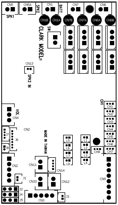
TTK80 V1
release EPM Setting and limitation
|
EPM No., Application |
ESC
mode
ESC/Ultrasonic ESC port |
PWM mode
PWM port |
|
EPM1
For Gun Elevation |
CN9.5
CN9.6 |
J4 |
|
EPM2
For Turret
rotation
|
CN9.7
CN9.8
|
J5
|
|
EPM3,
ESC1 |
CN6 |
N/A |
|
EPM4,
ESC2
|
CN7 |
N/A
|
TTK80SP/SPG V1(
2022/03/02 update )
|
Connector
|
Description
|
Main Gun Recoil Mode
is set to AirSoft or HL Recoil Mode |
Main Gun Recoil Mode
is set to TAMIYA Recoil Mode |
|
SW |
Switch Cable Port |
HL tank already have power switch on battery cable path, so
additional switch is no longer required, just to short
pins in this port by jumper or connect to a switch cable and keep it switched
on. |
|
CH1
(2/x)
|
TK-LINK RX
|
1. Battery - (Black Wire),
connect to
Battery -
on TCK board
2.
N/C
3.
TK-LINK RX (White wire), connect to
the TK-LINK TX pin on TCK board |
|
CH2
(1/1)
|
TK-LINK TX
|
1. Battery - (Black Wire),
connect to
Battery -
on TCK board
2.
N/C
3.
TK-LINK TX (White wire), connect to
the TK-LINK TX pin on TCK board |
|
CH3
(1/1)
|
CH3 control
signal |
N/C
* For V1
release |
|
CH4
(3/3)
|
CH5 control
signal
|
N/C |
|
CH5
(3/3) |
CH5 control
signal |
N/C |
|
CH6
(3/2) |
CH6 control
signal |
N/C |
|
CH7
(2/2) |
CH7 control
signal |
N/C |
|
CH8
(2/2) |
CH8 control
signal |
GBS Indicator |
|
CN1
|
Battery Power
|
1. Battery +
2.
Battery -
|
|
CN2 |
Infrared Port |
1.
HBU/TBU +
2.
HBU/TBU SIG
3.
HBU/TBU -
4. TBU FLASH LED -
5. TBU FLASH LED +
TBU FLASH LED
is the LED on Tamiya battle unit or IR configuration Line
, which
indicate the IR battle status or the setting just
set during
Tank Personalization |
|
CN3 |
Gun
Flash Port |
1. Battery +
2.
Strobe Trigger
3.
Battery -
4. HL AirSoft/Recoil Unit Switch
5. HL AirSoft/Recoil Unit Switch |
1. Battery +
2.
Strobe Trigger
3.
Battery -
4. TAMIYA Recoil Unit Switch
5. TAMIYA Recoil Unit Switch |
|
CN4 |
Sound
Volume |
1.
Volume Signal
Output (
Wiper pin of VR
)
2. Battery -( 1 outside pin of
VR )
3.
Volume
Signal
Input (
1 outside pin of VR )
|
|
CN5 |
Speaker |
1.
Speaker -
2.
Speaker +
TTK Speaker generates following sounds
|
|
CN6
(2/2)
|
ESC1
|
1.
Motor +
2.
Motor -
|
|
CN6-A |
ESC1
Additional Pad
|
When 540 or 550 Motor is used
for track driving, use this pad to connect motor |
|
CN6-B |
ESC1
Additional Pad
|
When 540 or 550 Motor is used
for track driving, use this pad to connect motor |
|
CN7
(x/1)
|
ESC2 |
1.
Motor +
2.
Motor -
|
|
CN7-A |
ESC2
Additional Pad
|
When 540 or 550 Motor is used
for track driving, use this pad to connect motor |
|
CN7-B |
ESC2
Additional Pad
|
When 540 or 550 Motor is used
for track driving, use this pad to connect motor |
|
CN9 |
Upper
Hull Functions
(
Turn, Lift, Shoot, Light) |
1. MG1 LED-
2. GBS CALI LED-
3.
-
MG
LED+
-
GBS CALI
LED+
-
AIRSOFT/RECOIL Motor+
4. AIRSOFT/RECOIL Motor-
5. Elevation Motor
6. Elevation Motor
7. Turret Motor
8. Turret Motor
*MG1
LED is also TK-Link RX Error indicator and turned on if not data received.
*GBS
CALI LED is GBS calibration indicator and turned on during
calibration,
|
1.
MG1 LED-
2. GBS CALI LED-
3.
4. TAMIYA Recoil unit white Wire
5. Elevation Motor
6. Elevation Motor
7. Turret Motor
8. Turret Motor/ EPM4.ESC
*MG1
LED is also TK-Link RX Error indicator and turned on if not data received.
*GBS
CALI LED is GBS calibration indicator and turned on during
calibration
|
|
CN10 |
NA |
N/C |
|
CN11 |
NA |
N/C |
|
CN12 |
NA
|
N/C |
|
CN13 |
SPK2 IN
|
1.Signal
2.
Battery - (Black Wire)
|
|
CN14 |
S.BUS
Port |
1. Battery - (Black Wire)
2.
+5V ( Red Wire)
3. Signal( White Wire)
4. NC
|
|
J1 |
IR Battle Emitter
Port |
To work
with IR battle emitter(IR010)
1. IR LED +
2. IR LED - |
|
J2
(5/5) |
RealRecoilTM
Servo Port |
1. Signal( White Wire)
2.
+5V ( Red Wire)
3. Battery - (Black Wire)
See
RealRecoil section in Assembly Guide |
|
J3 |
Cannon LED Flasher Port |
When
firing cannon, this LED is turned on then off to simulate nozzle flash
1. LED +
2. LED - |
|
J4
(1/4) |
Gun Elevation Servo
Port |
1. Signal( White Wire)
2.
+5V ( Red Wire )
3. Battery - (Black Wire) |
|
J5
(3/3) |
Turret Servo Port
|
1. Signal( White Wire)
2.
+5V ( Red Wire )
3. Battery - (Black Wire) |
|
J6 |
Programming and GBS Port |
To connect Programmer or GBS
unit |
|
J7 |
|
|
|
J8 |
Engine Deck Level Switch
|
1.
SWITCH
2.
SWITCH
|
|
L1 |
Rotating Light LED1
|
Rotating Light
are LEDs which is turned on and off sequentially
, LED1 ON --> LED1 Off --> LED2 ON --> LED2 Off --> LED3 ON --> LED3 Off
--> LED1 ON ........
1. LED +
2. LED - |
|
L2 |
Rotating Light LED2
|
1. LED +
2. LED - |
|
L3 |
Rotating Light LED3
|
1. LED +
2. LED - |
|
L4 |
Turret Controlled Switch/
Tail Light |
1. Device +
2. Device -
Maximum Current : 7A
*Need
200ohm in-serial resistor when connecting LED |
|
L5 |
MG2 |
1. LED +
2. LED - |
|
L6 |
Audio AMP Status LED |
Connect
to a LED to show the status of AMP, when CPU tune on
Audio AMP,
this LED is ON
1. LED +
2. LED -
|
|
L7 |
Aux Light 1 |
1. LED +
2. LED - |
|
L8 |
Aux
Light 2 |
1. N/C
2. N/C |
TTK80 V2
release EPM Setting and limitation
|
EPM No., Application |
ESC
mode
ESC/Ultrasonic ESC port |
PWM mode
PWM port |
|
EPM1, ESC3, (*4)
For Gun Elevation |
CN9.5
CN9.6(*4) |
J4(*4) |
|
EPM2,
ESC4
For Turret
rotation
|
CN7(*1)
|
CH3(*1)
(Only available in None GBS version )
|
|
EPM3,
ESC1
For
RWS rotation |
CN6(*2) |
N/A |
|
EPM4,
ESC2
For
RWS elevation
|
CN9.7
CN9.8(*3)
|
J5(*3)
|
TTK80SP/SPG V2(
2022/03/02 update )
|
Connector
|
Description
|
Main Gun Recoil Mode
is set to AirSoft or HL Recoil Mode |
Main Gun Recoil Mode
is set to TAMIYA Recoil Mode |
|
SW |
Switch Cable Port |
HL tank already have power switch on battery cable path, so
additional switch is no longer required, just to short
pins in this port by jumper or connect to a switch cable and keep it switched
on. |
|
CH1
(2/x)
|
TK-LINK RX
|
1. Battery - (Black Wire),
connect to
Battery -
on TCK board
2.
N/C
3.
TK-LINK RX (White wire), connect to
the TK-LINK TX pin on TCK board |
|
CH2
(1/1)
|
TK-LINK TX
|
1. Battery - (Black Wire),
connect to
Battery -
on TCK board
2.
N/C
3.
TK-LINK TX (White wire), connect to
the TK-LINK TX pin on TCK board |
|
CH3
(1/1)
|
EPM2.PWM |
EPM2.PWM
1. Battery
- (Black Wire)
2.
+5V ( Red Wire)
3. Signal(
White Wire)
*V2
release
|
|
CH4
(3/3)
|
TK-LINK RX
Indicator
|
Connect to a LED to
show the status of TK-Link data receiving.
Indicator is
turned OFF when data is received correctly
Indicator is
turned On when data is NOT received correctly
1.
N/C
2. ---> 200 ohm resistor ---> LED +
3. LED -
|
|
CH5
(3/3) |
CH5 control
signal |
|
|
CH6
(3/2) |
CH6 control
signal |
N/C |
|
CH7
(2/2) |
CH7 control
signal |
N/C |
|
CH8
(2/2) |
CH8 control
signal |
GBS Indicator |
|
CN1
|
Battery Power
|
1. Battery +
2.
Battery -
|
|
CN2 |
Infrared Port |
1.
HBU/TBU +
2.
HBU/TBU SIG
3.
HBU/TBU -
4. TBU FLASH LED -
5. TBU FLASH LED +
TBU FLASH LED
is LED on Tamiya battle unit or IR configuration Line
, which
indicate the IR battle status or the setting just
set during
Tank Personalization |
|
CN3 |
Gun
Flash Port |
1. Battery +
2.
Strobe Trigger
3.
Battery -
4. HL AirSoft/Recoil Unit Switch
5. HL AirSoft/Recoil Unit Switch |
1. Battery +
2.
Strobe Trigger
3.
Battery -
4. TAMIYA Recoil Unit Switch
5. TAMIYA Recoil Unit Switch |
|
CN4 |
Sound
Volume |
1.
Volume Signal
Output (
Wiper pin of VR
)
2. Battery -( 1 outside pin of
VR )
3.
Volume
Signal
Input (
1 outside pin of VR )
|
|
CN5 |
Speaker |
1.
Speaker -
2.
Speaker +
TTK Speaker generates following sounds
|
|
CN6
(2/2)
|
EPM3.ESC
|
1.
Motor +
2.
Motor -
|
|
CN6-A |
EPM3.ESC
Additional Pad
|
When 540 or 550 Motor is used
for track driving, use this pad to connect motor |
|
CN6-B |
EPM3.ESC
Additional Pad
|
When 540 or 550 Motor is used
for track driving, use this pad to connect motor |
|
CN7
(x/1)
|
EPM2.ESC |
1.
Motor +
2.
Motor -
|
|
CN7-A |
EPM2.ESC
Additional Pad
|
When 540 or 550 Motor is used
for track driving, use this pad to connect motor |
|
CN7-B |
EPM2.ESC
Additional Pad
|
When 540 or 550 Motor is used
for track driving, use this pad to connect motor |
|
CN9 |
Upper
Hull Functions
(
Turn, Lift, Shoot, Light) |
1. TTK.MG1 LED-
2. GBS CALI LED-
3.
-
MG1
LED+
-
GBS CALI
LED+
-
AIRSOFT/RECOIL Motor+
4. AIRSOFT/RECOIL Motor-
5. TTK.EPM1.ESC
6. TTK.EPM1.ESC
7. TTK.EPM4.ESC
8. TTK.EPM4.ESC
*MG LED is also TK-Link RX Error indicator and turned on if not data
received.
*GBS
CALI LED is aGBS calibration indicator and turned on during
calibration
|
1.
TTK.MG1
LED-
2. GBS CALI LED-
3.
4. TAMIYA Recoil unit white Wire
5. TTK.EPM1.ESC
6. TTK.EPM1.ESC
7. TTK.EPM4.ESC
8. TTK.EPM4.ESC
*MG LED is also TK-Link RX Error indicator and turned on if not data
received.
*GBS
CALI LED is GBS calibration indicator and turned on during
calibration
|
|
CN10 |
N/A |
|
|
CN11 |
N/A |
|
|
CN12 |
Aux Light 2
Tested
OK |
Pin 1 is
connected to Battery + when turned on
Pin 2 is
always Battery -
If connect to LED
1
--> 200 ohm resistor --> LED+
2. LED-
If connect to
Rotating Light Module
1.
-->
5V regulator -->
Rotating Light Module port +
2.
Rotating Light Module port -
|
|
CN13 |
SPK2 IN
|
1.Signal
2.
Battery - (Black Wire)
|
|
CN14 |
S.BUS
Port |
1. Battery - (Black Wire)
2.
+5V ( Red Wire)
3. Signal( White Wire)
4. NC
|
|
J1 |
IR Battle Emitter
Port |
To work
with IR battle emitter(IR010)
1. IR LED +
2. IR LED - |
|
J2
(5/5) |
RealRecoilTM
Servo Port |
1. Signal( White Wire)
2.
+5V ( Red Wire)
3. Battery - (Black Wire)
See
RealRecoil section in Assembly Guide |
|
J3 |
Cannon LED Flasher Port |
When
firing cannon, this LED is turned on then off to simulate nozzle flash
1. LED +
2. LED - |
|
J4 |
Gun Elevation Servo
Port/
TTK.EPM1.PWM |
1. Signal( White Wire)
2.
+5V ( Red Wire )
3. Battery - (Black Wire) |
|
J5 |
TTK.EPM4.PWM
|
1. Signal( White Wire)
2.
+5V ( Red Wire )
3. Battery - (Black Wire) |
|
J6 |
Programming and GBS Port |
To connect Programmer or GBS
unit |
|
J7 |
|
|
|
J8 |
Engine Deck Level Switch
|
1.
SWITCH
2.
SWITCH
|
|
L1 |
Rotating Light LED1
|
Rotating Light
are LEDs which is turned on and off sequentially
, LED1 ON --> LED1 Off --> LED2 ON --> LED2 Off --> LED3 ON --> LED3 Off
--> LED1 ON ........
1. LED +
2. LED - |
|
L2 |
Rotating Light LED2
|
1. LED +
2. LED - |
|
L3 |
Rotating Light LED3
|
1. LED +
2. LED - |
|
L4 |
Turret Controlled Switch/
Tail Light |
1. Device +
2. Device -
Maximum Current : 7A
*Need
200ohm in-serial resistor when connecting LED |
|
L5 |
TTK.MG2 |
1. LED +
2. LED - |
|
L6 |
Audio AMP Status LED |
Connect
to a LED to show the status of AMP, when CPU tune on
Audio AMP,
this LED is ON
1. LED +
2. LED -
|
|
L7 |
-- |
1. NC
2. NC |
|
L8 |
-- |
1. NC
2. NC |
TTK80SP/SPG V3(
2023/01/10 update )
|
Connector
|
Description
|
Main Gun Recoil Mode
is set to AirSoft or HL Recoil Mode |
Main Gun Recoil Mode
is set to TAMIYA Recoil Mode |
|
SW |
Switch Cable Port |
HL tank already have power switch on battery cable path, so
additional switch is no longer required, just to short
pins in this port by jumper or connect to a switch cable and keep it switched
on. |
|
CH1
(2/x)
|
TK-LINK RX
|
1. Battery - (Black Wire),
connect to
Battery -
on TCK board
2.
N/C
3.
TK-LINK RX (White wire), connect to
the TK-LINK TX pin on TCK board |
|
CH2
(1/1)
|
TK-LINK TX
|
1. Battery - (Black Wire),
connect to
Battery -
on TCK board
2.
N/C
3.
TK-LINK TX (White wire), connect to
the TK-LINK TX pin on TCK board |
|
CH3
(1/1)
|
EPM2.PWM |
EPM2.PWM
1. Battery
- (Black Wire)
2.
+5V ( Red Wire)
3. Signal(
White Wire)
*V2
release
|
|
CH4
(3/3)
|
TK-LINK RX
Indicator
|
Connect to a LED to
show the status of TK-Link data receiving.
Indicator is
turned OFF when data is received correctly
Indicator is
turned On when data is NOT received correctly
1.
N/C
2. ---> 200 ohm resistor ---> LED +
3. LED -
|
|
CH5
(3/3) |
CH5 control
signal |
|
|
CH6
(3/2) |
CH6 control
signal |
N/C |
|
CH7
(2/2) |
CH7 control
signal |
N/C |
|
CH8
(2/2) |
CH8 control
signal |
GBS Indicator |
|
CN1
|
Battery Power
|
1. Battery +
2.
Battery -
|
|
CN2 |
Infrared Port |
1.
HBU/TBU +
2.
HBU/TBU SIG
3.
HBU/TBU -
4. TBU FLASH LED -
5. TBU FLASH LED +
TBU FLASH LED
is LED on Tamiya battle unit or IR configuration Line
, which
indicate the IR battle status or the setting just
set during
Tank Personalization |
|
CN3 |
Gun
Flash Port |
1. Battery +
2.
Strobe Trigger
3.
Battery -
4. HL AirSoft/Recoil Unit Switch
5. HL AirSoft/Recoil Unit Switch |
1. Battery +
2.
Strobe Trigger
3.
Battery -
4. TAMIYA Recoil Unit Switch
5. TAMIYA Recoil Unit Switch |
|
CN4 |
Sound
Volume |
1.
Volume Signal
Output (
Wiper pin of VR
)
2. Battery -( 1 outside pin of
VR )
3.
Volume
Signal
Input (
1 outside pin of VR )
|
|
CN5 |
Speaker |
1.
Speaker -
2.
Speaker +
TTK Speaker generates following sounds
|
|
CN6
(2/2)
|
EPM3.ESC
|
1.
Motor +
2.
Motor -
|
|
CN6-A |
EPM3.ESC
Additional Pad
|
When 540 or 550 Motor is used
for track driving, use this pad to connect motor |
|
CN6-B |
EPM3.ESC
Additional Pad
|
When 540 or 550 Motor is used
for track driving, use this pad to connect motor |
|
CN7
(x/1)
|
EPM2.ESC |
1.
Motor +
2.
Motor -
|
|
CN7-A |
EPM2.ESC
Additional Pad
|
When 540 or 550 Motor is used
for track driving, use this pad to connect motor |
|
CN7-B |
EPM2.ESC
Additional Pad
|
When 540 or 550 Motor is used
for track driving, use this pad to connect motor |
|
CN9 |
Upper
Hull Functions
(
Turn, Lift, Shoot, Light) |
1. TTK.MG1 LED-
2. GBS CALI LED-
3.
-
MG1
LED+
-
GBS CALI
LED+
-
AIRSOFT/RECOIL Motor+
4. AIRSOFT/RECOIL Motor-
5. TTK.EPM1.ESC
6. TTK.EPM1.ESC
7. TTK.EPM4.ESC
8. TTK.EPM4.ESC
*MG LED is also TK-Link RX Error indicator and turned on if not data
received.
*GBS
CALI LED is aGBS calibration indicator and turned on during
calibration
|
1.
TTK.MG1
LED-
2. GBS CALI LED-
3.
4. TAMIYA Recoil unit white Wire
5. TTK.EPM1.ESC
6. TTK.EPM1.ESC
7. TTK.EPM4.ESC
8. TTK.EPM4.ESC
*MG LED is also TK-Link RX Error indicator and turned on if not data
received.
*GBS
CALI LED is GBS calibration indicator and turned on during
calibration
|
|
CN10 |
N/A |
|
|
CN11 |
N/A |
|
|
CN12 |
Aux Light 2
Tested
OK |
Pin 1 is
connected to Battery + when turned on
Pin 2 is
always Battery -
If connect to LED
1
--> 200 ohm resistor --> LED+
2. LED-
If connect to
Rotating Light Module
1.
-->
5V regulator -->
Rotating Light Module port +
2.
Rotating Light Module port -
|
|
CN13 |
SPK2 IN
|
1.Signal
2.
Battery - (Black Wire)
|
|
CN14 |
S.BUS
Port |
1. Battery - (Black Wire)
2.
+5V ( Red Wire)
3. Signal( White Wire)
4. NC
|
|
J1 |
IR Battle Emitter
Port |
To work
with IR battle emitter(IR010)
1. IR LED +
2. IR LED - |
|
J2
(5/5) |
RealRecoilTM
Servo Port |
1. Signal( White Wire)
2.
+5V ( Red Wire)
3. Battery - (Black Wire)
See
RealRecoil section in Assembly Guide |
|
J3 |
Cannon LED Flasher Port |
When
firing cannon, this LED is turned on then off to simulate nozzle flash
1. LED +
2. LED - |
|
J4 |
Gun Elevation Servo
Port/
TTK.EPM1.PWM |
1. Signal( White Wire)
2.
+5V ( Red Wire )
3. Battery - (Black Wire) |
|
J5 |
TTK.EPM4.PWM
|
1. Signal( White Wire)
2.
+5V ( Red Wire )
3. Battery - (Black Wire) |
|
J6 |
Programming and GBS Port |
To connect Programmer or GBS
unit |
|
J7 |
|
|
|
J8 |
Engine Deck Level Switch
|
1.
SWITCH
2.
SWITCH
|
|
L1 |
Rotating Light LED1
|
Rotating Light
are LEDs which is turned on and off sequentially
, LED1 ON --> LED1 Off --> LED2 ON --> LED2 Off --> LED3 ON --> LED3 Off
--> LED1 ON ........
1. LED +
2. LED - |
|
L2 |
Rotating Light LED2
|
1. LED +
2. LED - |
|
L3 |
Rotating Light LED3
|
1. LED +
2. LED - |
|
L4 |
Turret Controlled Switch/
Tail Light |
1. Device +
2. Device -
Maximum Current : 7A
*Need
200ohm in-serial resistor when connecting LED |
|
L5 |
TTK.MG2 |
1. LED +
2. LED - |
|
L6 |
Audio AMP Status LED |
Connect
to a LED to show the status of AMP, when CPU tune on
Audio AMP,
this LED is ON
1. LED +
2. LED -
|
|
L7 |
-- |
1. NC
2. NC |
|
L8 |
-- |
1. NC
2. NC |
TCK80S
|
EPM No. |
ESC/Ultrasonic ESC port |
PWM port |
|
EPM1 |
5th and 6th Pin of CN9 |
J4 |
|
EPM2
|
7th and 8th Pin of CN9
Note:ESC
in EPM2 is
Ultrasonic ESC |
J5 |
|
Connector
|
Description
|
Main Gun Recoil Mode
is set to AirSoft or HL Recoil Mode |
Main Gun Recoil Mode
is set to TAMIYA Recoil Mode |
|
SW |
Switch Cable Port |
HL tank already have power switch on battery cable path, so
additional switch is no longer required, just to short
pins in this port by jumper or connect to a switch cable and keep it switched
on. |
|
CH1
(2/x)
|
TK-LINK RX
|
1. Battery - (Black Wire),
connect to
Battery -
on TTK board
2.
N/C
3.
TK-LINK RX (White wire), connect to
the TK-LINK TX pin on TTK board |
|
CH2
(1/1)
|
TK-LINK TX
|
1. Battery - (Black Wire),
connect to
Battery -
on TTK board
2.
N/C
3.
TK-LINK TX (White wire), connect to
the TK-LINK TX pin on TTK board |
|
CH3
(1/1)
|
CH3 control
signal
|
Motor Right (CN6) External ESC control port
1. Battery - (Black Wire)
2.
+5V ( Red Wire )
3. Signal( White Wire)
|
|
CH4
(3/3)
|
TK-LINK RX
Indicator
|
Connect to a LED to
show the status of TK-Link data receiving.
Indicator is
turned OFF when data is received correctly
Indicator is
turned On when data is NOT received correctly
1.
N/C
2. ---> 200 ohm resistor ---> LED +
3. LED - |
|
CH5
(3/3) |
CH5 control
signal |
N/A |
|
CH6
(3/2) |
CH6 control
signal |
N/A |
|
CH7
(2/2) |
CH6
(C6)
|
Motor Left (CN7) External ESC control port
1. Battery - (Black Wire)
2.
+5V ( Red Wire )
3. Signal( White Wire)
|
|
CH8
(2/2) |
CH8 control
signal |
N/A |
|
CN1
|
Battery Power
|
1. Battery +
2.
Battery -
|
|
CN2 |
Infrared Port |
For IR programming port
1.
HBU/TBU +
2.
HBU/TBU SIG
3.
HBU/TBU -
4. TBU FLASH LED -
5. TBU FLASH LED +
TBU FLASH LED
is LED on Tamiya battle unit or IR configuration Line
, which
indicate the IR battle status or the setting
just set during
Tank Personalization |
|
CN3 |
N/A |
|
|
CN4 |
Sound
Volume |
1.
Volume Signal
Output (
Wiper pin of VR
)
2. Battery -( 1 outside pin of
VR )
3.
Volume
Signal
Input (
1 outside pin of VR )
|
|
CN5 |
Speaker |
1.
Speaker -
2.
Speaker +
TCK Speaker generate following sounds
-
Hull
mount machine gun( for WWII tank)
-
Engine
start
-
Engine
revving
-
Engine
stop
-
Turn
indicator
-
Horn(
for Leopard II tank)
-
Hydraulic sound( for ESC3 and ESC4 on Chassis control board )
|
|
CN6
|
Motor Left Track
|
|
|
CN6-A |
Motor Left Additional Pad
|
When 540 or 550 Motor is used
for track driving, use this pad to connect motor |
|
CN6-B |
Motor Left Additional Pad
|
When 540 or 550 Motor is used
for track driving, use this pad to connect motor |
|
CN7
|
Motor
Right |
|
|
CN7-A |
Motor Right Additional Pad
|
When 540 or 550 Motor is used
for track driving, use this pad to connect motor |
|
CN7-B |
Motor
Right
Additional Pad
|
When 540 or 550 Motor is used
for track driving, use this pad to connect motor |
|
CN9 |
Multi-Function
Port |
1. TCK.MG
LED-
2. Head Light LED-
3.
TCK.MG
LED+,
Head Light LED+
4. N/C
5. TCK.EPM1.ESC
6. TCK.EPM1.ESC
7. TCK.EPM2.ESC
8. TCK.EPM2.ESC
Maximum Current for Aux Device 2 port : 7A
*Need
200ohm in-serial resistor when connecting LED
*MG LED is also TK-Link RX Error indicator and turned on if not data
received.
|
|
CN10 |
Smoke
Unit /
Smoke
Heater |
1.
Smoke Unit + / Smoke Unit Heater
+
2.
Smoke Unit - / Smoke Unit Heater
-
|
|
CN11 |
Smoke
Unit /
Smoke
Heater switch |
1.
Switch
2.
Switch
|
|
CN12 |
Smoke
Unit/ Fan
|
1.
Fan +
2.
Fan -
|
|
CN13 |
SPK2 IN
|
1.Signal
2.
Battery - (Black Wire)
|
|
CN14 |
S.BUS
Port |
1. Battery - (Black Wire)
2.
+5V ( Red Wire)
3. Signal( White Wire)
4. NC
|
|
J1 |
N/A |
N/C |
|
J2 |
N/A |
N/C |
|
J3 |
Sound Pack
Processing
Indicator |
Flashing
when CPU processing sound pack
1. LED +
2. LED - |
|
J4 |
TCK.EPM1.ESC |
1. Signal( White Wire)
2.
+5V ( Red Wire )
3. Battery - (Black Wire) |
|
J5 |
TCK.EPM2.ESC
|
1. Signal( White Wire)
2.
+5V ( Red Wire )
3. Battery - (Black Wire) |
|
J6 |
Programmer Port |
To connect sound programmer |
|
J7 |
|
|
|
J8 |
N/A
|
N/A |
|
L1 |
AUX Light L1
|
1. LED +
2. LED - |
|
L2 |
AUX Light L2
|
1. LED +
2. LED - |
|
L3 |
AUX Light L3
|
1. LED +
2. LED - |
|
L4 |
Controlled SW/Tail Light |
When
connect to a motor:
1. Motor +
2. Motor -
When connect to a
LED:
1. 200ohm in-serial resistor --> LED +
2. LED -
* DC to DC regulator is need
if the device connected can't take battery + voltage.
* Maximum Current : 7A |
|
L5 |
AUX
Light
B/
MG-RSW switch Indicator
|
1. LED +
2. LED -
*Can
be the position light/side mark on Leopard 2 tank |
|
L6 |
Audio AMP Status LED |
Connect
to a LED to show the status of AMP, when CPU tune on
Audio AMP,
this LED is ON
1. LED +
2. LED -
|
|
L7 |
Right Blinker( Modern Tank) |
1. LED +
2. LED - |
|
L8 |
Left Blinker( Modern Tank) |
1. LED +
2. LED - |
Install guide
Tank Personalization
Settings
of TK series board can be changed by
Configuration IR REMOTE
as IR command transmitter, and TAMIYA battle unit(TBU),
Heng-Leog battle
unit(HBU), or our programming line as IR command receiver.
`
 Steps
to change settings:
Steps
to change settings:
STEP 1:
Turn power off, Turn power off, Turn power off,
STEP 2: Plug programming line/TBU/HBU
through TBU/HBU base into
CN2 Infrared Port
,
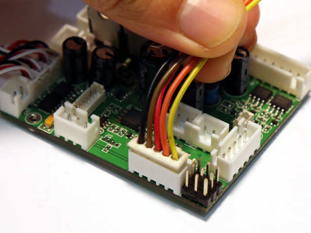
STEP 2: Install a jumper to J2
as shown below, Turn power on,
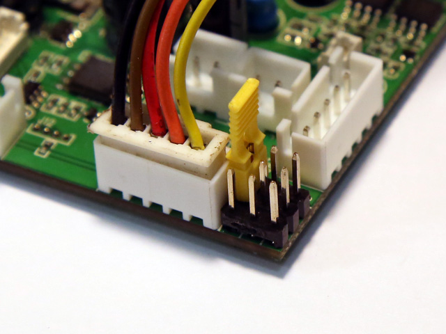
STEP 4:Refer to function
table listed below, point
Configuration IR REMOTE
to TBU/HBU/Programming line receiver,
and press the
button
of
setting
that you want to change,
"*"
sign in
function table
means the default setting that is programmed in factory
STEP 5: Indicator on
TBU/HBU flashes according to new
setting value.
STEP 6:
turn power off, remove jumper on J2, then
turn power on and TK board runs with new settings.
Available Settings
可用的設定
All
Available settings are separated in 4 function pages,
have to set to right page before changing specific setting by using
Function page
selection
Some settings that marked in
different back ground color can be set by different key in different function
page.
Available
settings general table for TTK
Available
settings general table for TCK
Function page
selection:
Press "-/--" Key on IR Configuration Remote to
select.
|
Available settings
選項 |
Indicator
flashes times
指示燈閃爍次數 |
Description
說明 |
|
Select
settings on Page 1 |
1* |
TK board
goes back to this page after power on |
|
Select settings on Page 2
|
2 |
|
|
Select settings on Page 3
|
3 |
|
|
Select settings on Page 4 |
4 |
|
*Text in black means that
setting function is on page1.
Function page 1
Save
current setting to PRESET 1: Press number
key "1" on IR Configuration Remote to save,
|
Available Settings |
Indicator
flashes times |
Description |
|
Save to
PRESET 1 |
1 |
Indicator flashes when setting
is saved
|
Save
current setting to PRESET 2: Press number
key "2" on IR Configuration Remote to save,
|
Available Settings |
Indicator
flashes times |
Description |
|
Save to
PRESET
2 |
2 |
Indicator flashes when setting
is saved
|
*Once
you've adjusted everything, you can
push "1" or
"2" to save
current setting to PRESET 1
or 2. If you don't do this saving the board remembers
the last settings.
Use saved
settings:
Press "ENT" or "SOUND MODE" Key on IR Configuration Remote to
select.
|
Available Settings |
Indicator
flashes times |
Description |
|
Use
PRESET 1
setting |
1 |
|
|
Use
PRESET 2 setting |
2 |
|
|
Use Factory Default Setting
( Read-Only ) |
3 |
To
restore factory
default value in case of setting data is messed up. |
*To
switch between the presets you press either "sound
mode" or "enter" button, once the preset is selected,
switch tank off and remove setup jumper. Switch back on and away you go.
TCK mixer mode:
Press  (MUTE) key on IR Configuration Remote to select( S.BUS version ).
|
Available Settings |
Indicator flashes times |
Description |
|
Mixer Mode
1 |
1* |
Tank mode 1
CH1 controls
rudder, CH2
controls throttle.
Proportional steering,
sharp and pivot turn* are supported
|
Left Track |
Right Track |
|
Pivot
Turn |
Sharp
Turn |
Proportional
Steering |
Proportional
Steering |
Sharp
Turn |
Pivot
Turn |
|
|
Mixer Mode
2 |
2 |
OFF mode
CH1
controls left track, CH2 controls right track
When
using triple differential gear box,
CH1
controls steering motor(CN6),
CH2
controls propulsion motor(CN7) |
|
Mixer Mode
3 |
3 |
Triple
differential gear box simulation
mode
CH1 controls
rudder, CH2
controls throttle.
Left
track speed = Throttle - rudder
Right
track speed = Throttle + rudder
|
|
Mixer Mode
4 |
4 |
Tank mode 2
CH1 controls
rudder, CH2
controls throttle,
Proportional steering and
sharp turn are supported
|
Left Track |
Right Track |
|
0%
Turn |
Proportional
Steering |
Proportional
Steering |
0%
Turn |
|
|
Mixer Mode
5 |
5 |
Half-Track mode 1
CH1 controls
rudder, CH2
controls throttle,
|
Left Track |
Right Track |
|
50%
Turn |
Proportional
Steering |
Proportional
Steering |
50%
Turn |
|
|
Mixer Mode
6 |
6 |
Half-Track mode 2
CH1 controls
rudder, CH2
controls throttle,
|
Left Track |
Right Track |
|
75%
Turn |
Proportional
Steering |
Proportional
Steering |
75%
Turn |
|
|
Mixer Mode
7 |
7 |
NA,Do
not select this mode |
|
Mixer Mode
8 |
8 |
NA,Do
not select this mode |
Main gun function
mode:
Press
"POWER" key
on IR Configuration Remote to select
Note: Available
Setting is ALWAYS from
TAMIYA Recoil MODE when power is
applied, then go to HL Airsoft Mode( indicator flashes 2 times) when
POWER key is pressed first time, It does
not means that the selected setting before power off is not saved.
|
Available Settings |
Indicator
flashes times |
Description |
|
TAMIYA RECOIL MODE* |
1* |
To use TAMIYA recoil unit,
CN3,
Pin4:TAMIYA
Recoil Unit Switch
CN3,
Pin5:TAMIYA
Recoil Unit Switch
CN9, Pin3:TAMIYA
Recoil Unit green Wire
CN9, Pin4:TAMIYA
Recoil Unit white Wire
|
|
HL AirSoft MODE |
2 |
To use HL AirSoft,
CN3,Pin4:HL
AirSoft Unit Switch
CN3,Pin5:HL
AirSoft Unit Switch
CN9,Pin3:HL AIRSOFT Motor +
CN9,Pin4:HL
AIRSOFT Motor -
|
|
NA |
3 |
Do not select this mode
|
|
NA |
4 |
Do not select this mode |
*Use this mode on Hooben Tank.
Upper
hull functions
(CN9) mode:
Press
"POWER" key
on IR Configuration Remote to select
※Available Setting is ALWAYS from
TAMIYA Recoil MODE when power is
applied, then go to HL Airsoft Mode( indicator flashes 2 times) when POWER key is pressed first time,
It does not means that the selected setting before power off is not saved.
|
Available Settings |
Indicator
flashes times |
Description |
|
TAMIYA Recoil MODE* |
1* |
To use TAMIYA recoil unit:
CN3,
Pin4:TAMIYA
Recoil Unit Switch
CN3,
Pin5:TAMIYA
Recoil Unit Switch
CN9, Pin3:TAMIYA
Recoil Unit green Wire
CN9, Pin4:TAMIYA
Recoil Unit white Wire
|
|
HL AirSoft MODE |
2 |
To use HL AirSoft:
CN3,Pin4:HL
AirSoft Unit Switch
CN3,Pin5:HL
AirSoft Unit Switch
CN9,Pin3:HL AIRSOFT Motor +
CN9,Pin4:HL
AIRSOFT Motor -
|
|
Asiatam Recoil Mode |
3 |
CN3,Pin4:Asiatam
Recoil Switch
CN3,Pin5:Asiatam
Recoil Switch
CN9,Pin3:
Asiatam Recoil Motor +
CN9,Pin4:
Asiatam Recoil Motor -
|
|
MG
Smoke
Mode※2 |
4 |
CN3,Pin4:NC
CN3,Pin5:NC
CN9,Pin3: Air
Pump +
CN9,Pin4: Air
Pump -
|
|
Reserved
AUX POWER CONTROL MODE |
5 |
CN3,Pin4:Not
connected
CN3,Pin5:Not
connected
CN9,Pin3:
Device +
CN9,Pin4:
Device -
※1
|
|
Servo Recoil Only MODE |
6 |
CN3,
Pin4:No function
CN3,
Pin5:No function
CN9, Pin3:No
function
CN9, Pin4:No
function
|
|
Cannon Smoke Mode※2 ※4 |
7 |
CN3,
Pin4:No function
CN3,
Pin5:No function
CN9, Pin3:Air
Pump +
CN9, Pin3:Air
Pump -
|
|
MG2
Mode※3 |
8 |
CN3,Pin4:NC
CN3,Pin5:NC
CN9,Pin3: Air
Pump +/ MG2 LED+
CN9,Pin4: Air
Pump -/ MG2 LED -
|
※1
Only available if AUX Power control Voltage of CN9 Pin 3 is equal to battery voltage
※2
V2.2 and above
※3
available on TK50 and TK50P version V2.3 and above
※4
TK50PG2 default setting
Receive TAMIYA IR
code:
press
"TV/VIDEO" or "->[]" Key on IR
Configuration Remote to select
|
Available Settings |
Indicator
flashes times |
Description |
|
Enabled |
1* |
Tank react to
TAMIYA IR code |
|
Disabled |
2 |
|
Receive HL IR code:
press
"VOL DOWN" Key on IR
Configuration Remote to select
|
Available Settings |
Indicator
flashes times |
Description |
|
Enabled |
1* |
Tank react to HL IR
code, |
|
Disabled |
2 |
|
IR
battle preset
data: press "MTS"
or "A/B" Key on IR Configuration Remote to select
|
Available Settings |
Indicator
flashes times |
Description |
|
TAMIYA Heavy tank |
1* |
Reload Time = 9 seconds,
Invulnerability time = 10 seconds,
Max. hit can
take = 9 hit. |
|
TAMIYA
Medium tank |
2 |
Reload Time = 5 seconds,
Invulnerability time = 12 seconds,
Max. hit can
take = 6 hits |
|
TAMIYA
Light tank |
3 |
Reload Time = 3 seconds,
Invulnerability time = 15 seconds,
Max. hit can
take = 3 hits. |
|
Heavy Armored Vehicle |
4 |
Invulnerability time = 10 seconds,
Max. cannon hit cam take = 1 hit
Max. machine gun hit can take = 24 hit. |
|
Medium
Armored Vehicle |
5 |
Invulnerability time = 10 seconds,
Max. cannon hit can take = 1 hit
Max. machine gun hit can take = 16 hit. |
|
Light
Armored Vehicle
|
6 |
Invulnerability time = 10 seconds,
Max. cannon hit can take = 1 hit
Max. machine gun hit can take = 8 hit. |
|
HL tank |
7 |
Reload Time = 3 seconds,
Invulnerability time = 10 seconds(Note1)
Max. hit can
take = 5 hits, |
|
Reserved |
8 |
|
Note1: Reference setting for HL
Tank
Momentum effect
on/off:
Press "SLEEP(0x36)"
or " " on IR Configuration Remote to
select " on IR Configuration Remote to
select
|
Available Settings |
Indicator
flashes times |
Description |
|
Off |
1* |
|
|
ON |
2 |
|
*This function is only available
on TK22
Reload sound
on/off:
Press "Timer Off(0x3C)"
or "
 "on IR
Configuration Remote to select "on IR
Configuration Remote to select
|
Available Settings |
Indicator
flashes times |
Description |
|
On |
1* |
|
|
Off |
2 |
|
*This function
is only available on TTK
TCK
cannon sound
on/off:
Press "Timer Off(0x3C)"
or "
"on IR
Configuration Remote to select
|
Available Settings |
Indicator
flashes times |
Description |
|
On |
1* |
TCK
generates cannon sound when firing cannon |
|
Off |
2 |
|
*This function
is only available on TCK
TCK
taking
a hit hull recoil on/off(1):
Press "JUMP(0x3B)"
on IR Configuration Remote to
select
|
Available Settings |
Indicator
flashes times |
Description |
|
On |
1* |
|
|
Off |
2 |
|
*This function is only available
on TK22
Strength of
taking a hit hull
recoil:
Press "CH Up"
or "PROGR +" key
on IR Configuration Remote to select
|
Available Settings |
Indicator
flashes times |
Description |
|
1 |
1 |
Small( 1 ) to Large( 16
)movement |
|
: |
: |
|
6 |
6* |
|
: |
: |
|
16 |
16 |
Firing
tank gun
hull
recoil on/off:
Press "SURROUND(0x29)"
on IR Configuration Remote to select
|
Available Settings |
Indicator
flashes times |
Description |
|
On |
1* |
|
|
Off |
2 |
|
*This function is only available
on TK22
Strength of firing tank gun
hull
recoil:
Press
"VOL UP" key on IR
Configuration Remote to select
|
Available Settings |
Indicator
flashes times |
Description |
|
1 |
1 |
Small( 1 ) to Large( 16
)movement |
|
: |
: |
|
6 |
6* |
|
: |
: |
|
16 |
16 |
RealRecoil servo direction:
press "CH down"
or "PROGR -" key
on IR Configuration Remote to select
|
Available Settings |
Indicator
flashes times |
Description |
|
Normal |
1* |
|
|
Reversed |
2 |
|
Gun elevation servo direction:
press "
Teletext ON(0x3F)" or " "
key on IR Configuration
Remote to select "
key on IR Configuration
Remote to select
|
Available Settings |
Indicator
flashes times |
Description |
|
Normal |
1* |
|
|
Reversed |
2 |
|
*This function is only available
on TK22
Speed
reduction in damaged state:
press "3"
key on IR
Configuration Remote to select.
|
Available Settings |
Indicator
flashes times |
Description |
|
0% |
1 |
No mobility damage simulation, Speed is not
reduced when Tank is in damaged state. |
|
-12.5% |
2* |
|
|
-25% |
3 |
|
|
-37.5% |
4 |
|
|
-50% |
5 |
|
|
-62.5% |
6 |
|
|
-75% |
7 |
|
|
-87.5% |
8 |
|
Speed
reduction in
badly damaged
state:
press "DISPLAY"
"?" or "DRC-MF" key
on IR Configuration Remote to select.
|
Available Settings |
Indicator
flashes times |
Description |
|
0% |
1 |
No mobility damage simulation, Speed is not
reduced when Tank is in badly damaged state. |
|
-12.5% |
2 |
|
|
-25% |
3* |
|
|
-37.5% |
4 |
|
|
-50% |
5 |
|
|
-62.5% |
6 |
|
|
-75% |
7 |
|
|
-87.5% |
8 |
|
Armor type:
press number
key "9" on IR Configuration
Remote to select
|
Available Settings |
Indicator
flashes times |
Description |
|
Heavy Armor |
1* |
Resistance to machine gun
|
|
Soft
skin, like Trucks |
2 |
No resistance to machine gun
|
Sending IR code when firing machine gun:
press number
key "6" on IR Configuration
Remote to select
|
Available Settings |
Indicator
flashes times |
Description |
|
Not
to send
MG IR code
|
1* |
|
|
To send MG IR code |
2 |
|
Primary weapon reload time:
press number
key "4" on IR Configuration
Remote to select
|
Available Settings |
Indicator
flashes times |
Description |
|
3 seconds |
3 |
|
|
4 seconds |
4 |
|
|
5 seconds |
5 |
|
|
6 seconds |
6 |
|
|
7 seconds |
7 |
|
|
8 seconds |
8 |
|
|
9 seconds |
9* |
|
|
10
seconds |
10 |
|
|
11 seconds
|
11 |
|
|
12
seconds |
12 |
|
|
13
seconds |
13 |
|
|
14
seconds |
14 |
|
|
15
seconds |
15 |
|
Rounds of primary weapon:
press number
key "8" on IR Configuration
Remote to select,
|
Available Settings |
Indicator
flashes times |
Description |
|
Not
limited |
1* |
|
|
8 rounds |
2 |
|
|
16 rounds |
3 |
|
|
24 rounds |
4 |
|
|
32 rounds |
5 |
|
|
40 rounds |
6 |
|
|
48 rounds |
7 |
|
|
56 rounds |
8 |
|
|
64 rounds |
9 |
|
|
72 rounds |
10 |
|
|
80 rounds |
11 |
|
|
88 rounds |
12 |
|
|
96 rounds |
13 |
|
|
104 rounds |
14 |
|
|
112
rounds |
15 |
|
|
120
rounds |
16 |
|
Primary weapon IR code:
press number key "0" on IR
Configuration Remote to select
|
Available Settings |
Indicator
flashes times |
Description |
|
TAMIYA cannon code |
1* |
For TAMIYA IR battle |
|
HL cannon code |
2 |
For HL IR battle |
|
Repair
code
|
3 |
For Bergepanzer
application,
damage count decreased by 1 when this IR
code is received, each repair needs 15s, no other vehicle
can damage vehicle that is
under this mode |
|
Machine Gun code |
4 |
Vehicle
with MG |
Invulnerability time:
Vehicle is Invulnerable during
this period,
press number
key "7" on IR Configuration
Remote to select
|
Available Settings |
Indicator
flashes times |
Description |
|
Vehicle can not be recovered from destroyed mode |
1 |
|
|
1 second |
2 |
|
|
2 seconds |
3 |
|
|
3 seconds |
4 |
|
|
4 seconds |
5 |
|
|
5 seconds |
6 |
|
|
6 seconds |
7 |
|
|
7 seconds |
8 |
|
|
8 seconds |
9 |
|
|
9 seconds |
10 |
|
|
10
seconds |
11* |
TAMIYA
Heavy tank |
|
11
seconds
|
12 |
|
|
12
seconds |
13 |
TAMIYA
Medium tank |
|
13
seconds |
14 |
|
|
14
seconds |
15 |
TAMIYA
Light tank |
|
15
seconds |
16 |
|
Max hit can take:
Press number key "5"
on IR Configuration Remote to select
|
Available Settings |
Indicator
flashes times |
Description |
|
1 round |
1 |
|
|
2 rounds |
2 |
|
|
3 rounds |
3 |
TAMIYA
Light tank |
|
4 rounds |
4 |
|
|
5 rounds |
5 |
|
|
6 rounds |
6 |
TAMIYA
Medium tank |
|
7 rounds |
7 |
|
|
8 rounds |
8 |
|
|
9 rounds |
9* |
TAMIYA
Heavy tank |
|
10
rounds |
10 |
|
|
11
rounds |
11 |
|
|
12
rounds |
12 |
|
|
13
rounds |
13 |
|
|
14
rounds |
14 |
|
|
15
rounds |
15 |
|
Function page selection:
Press "-/--" Key on IR Configuration Remote to
select.
|
Available Settings |
Indicator
flashes times |
Description |
|
Select
settings on function page 1 |
1* |
TK board
goes back to this page after power on |
|
Select settings on function page 2
|
2 |
|
|
Select settings on function page 3
|
3 |
|
|
Select settings on function page 4 |
4 |
|
*Text in black means that
setting function is on page1.
Function page 2
Gun elevation EPM (TTK.EPM1) mode:
press "1"
key on IR configuration
remote to select
|
Available Settings |
Indicator
flashes times |
Description |
|
ESC Mode |
1* |
ESC1 enabled,
PWM1 disabled |
|
PWM Mode |
2 |
ESC1 disabled,
PWM1 enabled
*TK80X
default Setting |
*A Power on and off cycle( turn off power for
5 seconds then power on) is needed to active change after mode change.
Gun elevation servo(
TTK.EPM1. PWM) direction:
press "2"
key on TV remote to select
|
Available Settings |
Indicator
flashes times |
Description |
|
Normal |
1* |
|
|
Reversed |
2 |
*TK80X default Setting |
Turret
rotation/gun traverse EPM( TTK.EPM2 ) mode:
press "3"
key on IR configuration to
select
|
Available Settings |
Indicator
flashes times |
Description |
|
ESC Mode |
1* |
ESC2 enabled,
PWM2 disabled |
|
PWM Mode |
2 |
ESC2 disabled,
PWM2 enabled
*TK80X
default Setting |
*A Power on and off cycle( turn off power for
5 seconds then power on) is needed to active change after mode change.
Turret rotation servo (TTK.EPM2.PWM)
direction:
press "4"
key on IR configuration to
select
|
Available Settings |
Indicator
flashes times |
Description |
|
Normal |
1* |
|
|
Reversed |
2 |
|
TTK.EPM4 mode:
press "5"
key on IR configuration
remote to select
|
Available Settings |
Indicator
flashes times |
Description |
|
ESC Mode |
1* |
ESC port
enable, PWM port disable
|
|
PWM Mode |
2 |
ESC port
disable, PWM port enable |
*Available in V2 and above
TTK.EPM4
PWM direction:
press "7"
key on TV remote to select
|
Available Settings |
Indicator
flashes times |
Description |
|
Normal |
1* |
|
|
Reversed |
2 |
|
TCK.EPM1
mode:
press "
1" key
on IR configuration remote to select
|
Available Settings |
Indicator
flashes times |
Description |
|
ESC Mode |
1* |
ESC1 enabled, PWM1
disabled |
|
PWM Mode |
2 |
ESC1 disabled, PWM1
enabled |
*A Power on and off cycle( turn off power for
5 seconds then power on) is needed to active change after mode change.
TCK.EPM1.PWM
direction:
press "
2" key
on TV remote to select
|
Available Settings |
Indicator
flashes times |
Description |
|
Normal |
1* |
|
|
Reversed |
2 |
|
TCK.EPM2.PWM
mode:
press "
3" key
on IR configuration to select
|
Available Settings |
Indicator
flashes times |
Description |
|
ESC Mode |
1* |
ESC2 enabled, PWM2
disabled |
|
PWM Mode |
2 |
ESC2 disabled, PWM2
enabled |
*A Power on and off cycle( turn off power for
5 seconds then power on) is needed to active change after mode change.
TCK.EPM2.PWM
direction:
press "
4" key
on IR configuration to select
|
Available Settings |
Indicator
flashes times |
Description |
|
Normal |
1* |
|
|
Reversed |
2 |
|
TCK
taking
a hit hull recoil on/off(2) : Press "SLEEP"
on IR Configuration Remote to select
|
Available Settings |
Indicator
flashes times |
Description |
|
On |
1* |
|
|
Off |
2 |
|
※V2.3 and
above
Function page 3
Ultrasonic ESC
start voltage
increase:
Select page 3, press
"6" on IR Configuration Remote to increase level,
indicator flash once each time, indicator flash twice when reach maximum level
Ultrasonic ESC
start voltage
decrease:
Select page 3 , press
"3" on IR Configuration Remote to decrease level,
indicator flash once each time, indicator flash twice when reach minimun level
Ultrasonic ESC start voltage reset to zero:
Select page 3, press
"DISPLAY" or "?" Key on IR
Configuration Remote to reset start voltage,
indicator flash once every time.
Vertical GBS
enable :
Select page 3, press
"Timer off " Key on IR Configuration
Remote to select
|
Available Settings |
Indicator
flashes times |
Description |
|
Disable |
1 |
No vertical GBS |
|
Enable |
2* |
|
* V3 SW release
Elevation
servo speed reduction:
Select page 3, press
"SLEEP" Key on IR Configuration
Remote to select
|
Available Settings |
Indicator
flashes times |
Description |
|
Enable |
1* |
reduce servo speed to simulate
the elevation speed of real tank |
|
Disable |
2 |
No limitation |
* V3 SW release
GBS status indicator enable:
press
"TV/VIDEO" or "->[]" Key on IR
Configuration Remote to select
|
Available Settings |
Indicator
flashes times |
Description |
|
Enabled |
1* |
|
|
Disabled |
2 |
|
Elevation Sound Mode:
press
"SOUND Mode" Key on IR
Configuration Remote to select
|
Available Settings |
Indicator
flashes times |
Description |
|
ESC Mode |
1* |
Elevation Sound follows ESC, will
not stop until ESC is stopped |
|
Servo Mode |
2** |
Elevation Sound follows servo
movement, stops when reach both end.
Set to this mode when servo
elevation, auto load position and engine deck detection are turned on. |
*Default setting for none G2
variant
**Default setting for G2 variant
Vertical
GBS slow response gain
increase:
Select page 3 , press number
key "1" on IR Configuration Remote to increase gain
|
Available Settings |
Indicator
flashes times |
Description |
|
0 |
1 |
|
|
: |
: |
|
|
8 |
9 |
|
Vertical
GBS slow response gain
decrease:
Select page 3 , press number
key "4" on IR Configuration Remote to increase gain
|
Available Settings |
Indicator
flashes times |
Description |
|
0 |
1 |
|
|
: |
: |
|
|
8 |
9 |
|
Vertical
GBS fast response gain
increase:
Select page 3 , press number
key "2" on IR Configuration Remote to increase gain
|
Available Settings |
Indicator
flashes times |
Description |
|
0 |
1 |
|
|
: |
: |
|
|
8 |
9 |
|
Vertical
GBS fast response gain
decrease:
Select page 3 , press number
key "5" on IR Configuration Remote to increase gain
|
Available Settings |
Indicator
flashes times |
Description |
|
0 |
1 |
|
|
: |
: |
|
|
8 |
9 |
|
Vertical
GBS servo angle gain
increase:
Select page 3 , press number
key "8" on IR Configuration Remote to increase gain
|
Available Settings |
Indicator
flashes times |
Description |
|
0 |
1 |
|
|
: |
: |
|
|
8 |
9 |
|
Vertical
GBS servo angle gain
decrease:
Select page 3 , press number
key "0" on IR Configuration Remote to increase gain
|
Available Settings |
Indicator
flashes times |
Description |
|
0 |
1 |
|
|
: |
: |
|
|
8 |
9 |
|
Engine deck level
increase:
Select page 3 , press
"VOL UP" on IR Configuration Remote to increase level
Engine deck level
decrease:
Select page 3 , press
"VOL Down" on IR Configuration Remote to decrease level
Engine deck level
function enable:
Select page 3, press
"MUTE" Key on IR Configuration
Remote to select
|
Available Settings |
Indicator
flashes times |
Description |
|
Disable |
1 |
|
|
Enable |
2* |
|
Engine deck level
detection switch polarity
:
Select page 3, press
"JUMP" Key on IR Configuration
Remote to select
|
Available Settings |
Indicator
flashes times |
Description |
|
Normal Open switch |
1* |
Switch come with TK60G2
|
|
Normal Close switch |
2 |
TAMIYA switch |
Auto load position up:
Select page 3 , press
"CH UP" on IR Configuration Remote to increase level
Auto
load position
down:
Select page 3 , press
"CH Down" on IR Configuration Remote to decrease level
Auto load
position enable:
Select page 3, press
"POWER" Key on IR
Configuration Remote to select
|
Available Settings |
Indicator
flashes times |
Description |
|
Disable |
1 |
|
|
Enable |
2* |
|
Auto load position delay
time:
Select page 3 , press number
key "7" on IR Configuration Remote to select
|
Available Settings |
Indicator
flashes times |
Description |
|
1 |
1 |
1
second |
|
: |
: |
|
|
8 |
8 |
8
seconds |
V3 software release and
above
Auto load position duration:
Select page 3 , press number
key "9" on IR Configuration Remote to select
|
Available Settings |
Indicator
flashes times |
Description |
|
1 |
1 |
1
second |
|
: |
: |
|
|
16 |
16 |
16
seconds |
V3 software release and
above
Function page 4
Cannon smoke
duration:
Select page 4 , press number
key "7" on IR Configuration Remote to select
|
Available Settings |
Indicator
flashes times |
Description |
|
1 |
1 |
1
second |
|
: |
: |
|
|
8 |
8 |
8
seconds |
V3.1 software release and
above
Cannon
bore
evacuator effect
enable:
Select page 4, press
"POWER" Key on IR Configuration
Remote to select
|
Available Settings |
Indicator
flashes times |
Description |
|
Disable |
1 |
|
|
Enable |
2* |
|
V3.1 software release and
above
Cannon bore evacuator effect duration:
Select page 4 , press number
key "9" on IR Configuration Remote to select
|
Available Settings |
Indicator
flashes times |
Description |
|
1 |
1 |
1
second |
|
: |
: |
|
|
8 |
8 |
8
seconds |
V3.1 software release and
above
Damage level
of the hit taken from back(TCK.CN2)(1):
Select page 4, press "JUMP" key on IR Configuration Remote to change.
|
Available Settings |
Indicator
flashes times |
Description |
|
0 |
1 |
No damage. |
|
: |
: |
|
|
4 |
4* |
1 hit taken
form back equal to 4 hit taken |
|
: |
: |
|
|
15 |
15 |
|
Damage level
of the hit taken from back(TCK.CN2)(2):
Select page 4, press "DISPLAY" ,"?"
or "DRC-MF" key on IR Configuration Remote to change.
|
Available Settings |
Indicator
flashes times |
Description |
|
0 |
1 |
No damage. |
|
: |
: |
|
|
4 |
4* |
1 hit taken
form back equal to 4 hit taken |
|
: |
: |
|
|
15 |
15 |
|
V3.2 software release and
above
Horizontal GBS enable:
Select page 4 , press " Timer
off
" key on IR Configuration Remote to increase gain
|
Available Settings |
Indicator
flashes times |
Description |
|
Disable |
1 |
|
|
Enable |
2 |
|
Horizontal GBS motor P gain increase:
Select page 4 , press number
key "1" on IR Configuration Remote to increase gain
|
Available Settings |
Indicator
flashes times |
Description |
|
0 |
1 |
|
|
: |
: |
|
|
8 |
9 |
|
Horizontal GBS motor P gain
decrease:
Select page 4 , press number
key "4" on IR Configuration Remote to increase gain
|
Available Settings |
Indicator
flashes times |
Description |
|
0 |
1 |
|
|
: |
: |
|
|
8 |
9 |
|
Horizontal GBS motor I gain
increase:
Select page 4 , press number
key "2" on IR Configuration Remote to increase gain
|
Available Settings |
Indicator
flashes times |
Description |
|
0 |
1 |
|
|
: |
: |
|
|
8 |
9 |
|
Horizontal GBS motor I gain
decrease:
Select page 4 , press number
key "5" on IR Configuration Remote to increase gain
|
Available Settings |
Indicator
flashes times |
Description |
|
0 |
1 |
|
|
: |
: |
|
|
8 |
9 |
|
Horizontal GBS motor D gain increase:
Select page 4 , press number
key "3" on IR Configuration Remote to increase gain
|
Available Settings |
Indicator
flashes times |
Description |
|
0 |
1 |
|
|
: |
: |
|
|
8 |
9 |
|
Horizontal GBS motor D gain
decrease:
Select page 4 , press number
key "6" on IR Configuration Remote to increase gain
|
Available Settings |
Indicator
flashes times |
Description |
|
0 |
1 |
|
|
: |
: |
|
|
16 |
17 |
|
Horizontal GBS
dead band
increase:
Select page 4 , press number
key "8" on IR Configuration Remote to increase gain
|
Available Settings |
Indicator
flashes times |
Description |
|
0 |
1 |
|
|
: |
: |
|
|
8 |
9 |
|
Horizontal GBS
dead band
decrease:
Select page 4 , press number
key "0" on IR Configuration Remote to increase gain
|
Available Settings |
Indicator
flashes times |
Description |
|
0 |
1 |
|
|
: |
: |
|
|
16 |
17 |
|
|
Status read out and IR battle test via
Configuration IR
Remote |
Point
Configuration IR remote to TBU/HBU and press key listed below to show
vehicle status or test IR battle function.
No jumper should be installed on J1.
|
KEY on IR Configuration
Remote |
Description |
|
Number Key "1" |
To repair vehicle,
damage count decreased by 1 |
|
Number Key "2" |
Fire
cannon to vehicle |
|
Number Key "3" |
Fire machine gun to
vehicle |
|
Number Key "4" |
Number of flash indicate
remain hits
can take |
.
Use dry battery or power supply as
power source at testing to keep burn down anything if any error on modification.
then use chargeable battery when every function working normally.
Read
carefully and fully understand the instructions before commencing assembly.
Metal
part on FET can not be touched with any metal when TK board is operating.

MADE
IN TAIWAN
|