HL tank
already have power switch on battery cable path, so additional switch is
no longer required, just to short pins in this port by jumper
or connect to a switch cable and keep it switched on.
CN1
Battery
Power
1. Battery +
2.
Battery -
CN2
Infrared Port
1. HBU/TBU +
2. HBU/TBU SIG
3.
HBU/TBU -
4. TBU FLASH LED -
5. TBU FLASH LED +
CN3
Gun Flash
Port
1. Battery +
2. Strobe Trigger
3.
Battery -
4. Refer to Upper Hull Functions (CN9) Mode
Table
5. Refer to Upper Hull Functions (CN9) Mode
Table
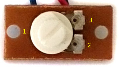
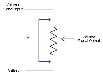
CN4
Sound Volume
1. Volume Signal
Output (
Wiper pin of VR
)
2. Battery -( 1 outside
pin of VR )
3.Volume
Signal
Input (
1 outside pin of VR )
CN5
Speaker
1.
Speaker -
2. Speaker +
CN6
Ultrasonic
ESC1
Connect to left track/steering motor
CN7
Ultrasonic ESC2
Connect to right track/propulsion
motor
CH1
S.BUS
RX
1. Battery -
2. +5V
3. Signal
CH2
後灯/尾燈
Aux Light 1
Connect to LED:
1. N/C
2. LED +
3.
LED -
CH3
警示灯
Aux Light 2
Connect to LED:
1. N/C
2. LED +
3.
LED -
CH4
搜索雷达
開關
Connect to a MOS模塊:
1. Battery -
2. Control signal
3.
Not connected
CN9
Upper Hull Functions
( Turn, Lift, Shoot,
Light)
1. MG1 LED-
双炮管 LED-
2. Head Light LED-
※1 頭燈LED -
3.
雙管砲冒烟空氣汞+
及頭燈LED +
4. 雙管砲冒烟空氣汞-
5. No connection
6. No connection
7. TURRET MOTOR
8. TURRET MOTOR
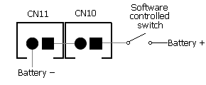
CN10
Smoke Unit
Connect to smoke unit
CN11
Smoke Unit
Hardware Switch
1.
SWITCH
2.
SWITCH
switch on to enable
CN10 port, off to disable CN10
Equivalent circuit of CN10 and CN11
J1
IR Battle Emitter
Port
To work with IR battle
emitter(IR010)
1. IR LED +
2. IR LED -
J2
RealRecoil Servo Port
RealRecoil Servo Port is always
turned ON, no setting is needed to turn it on
1. Signal( White Wire)
2. +5V ( Red Wire)
3. Battery - (Black Wire)
See RealRecoil section in
Assembly Guide
J3
Cannon Flash Port
1.
Cannon Flash
LED +
2.
Cannon Flash
LED -
J4
Gun Elevation Servo Port
1. Battery -
2. +5V
3. Signal
J5
Turret/Gun
traverse Servo
Port
1. Battery -
2. +5V
3. Signal
J6
Programming and GBS unit Port
To connect TK Programmer or
GBS unit
Gepard Upper
Hull Functions (CN9) Mode Table
Mode
CN9.3
CN9.4
CN3.4
CN3.5
双炮管
冒烟
MG1
Smoke
/Recoil
※
MG1 LED+
and
Head Light LED+
and
MG
Recoil
Solenoid+
/Air
Pump +
双炮管 LED+
及
雙管砲冒烟空氣汞+
MG
Recoil
Solenoid-
/Air Pump -
雙管砲冒烟空氣汞-
Not connected
Not connected
以下Don't
Care
Slip ring connection guide
Shared power wire
Power wire
Wire count
Description
Battery +
1
From CN3.1
Battery -
1
From CN3.3
+5V
1
From J5.2
Dedicated wire
Connector
Wire count
Description
Upper
Hull Functions (CN9) Mode
Airsoft
Tamiya Recoil
MG2
Recoil
Solenoid
CN2
3
Infrared Port
1.
+5V(share )
2. HBU/TBU SIG
3.
Battery - (share )
4. TBU FLASH LED -
5. TBU FLASH LED +
CN3
1
Gun Flash
Port
1. Battery + (share)
2. Strobe Trigger
3.
Battery - (share )
4. AirSoft/Recoil Switch
5. +5V(share )
1. Battery + (share)
2. Strobe Trigger
3.
Battery -
(share)
4. TAMIYA Recoil Unit Switch
5.+5V
1. Battery +
(share)
2. Strobe Trigger
3.
Battery -
(share)
4. Not connected
5. +5V
CH2
1
AUX LIGHT 1
Connect to LED:
1. NC
2. LED+ ( +5V share )
3.
LED-
CH3
1
AUX LIGHT2
Connect to LED:
1. N/C
2. LED+ ( +5V share )
3.
LED -
CH4
1
MG2 LED
Connect to LED:
1. N/C
2. LED+ ( +5V share )
3.
LED -
CN9
6
Upper Hull Functions
( Turn, Lift, Shoot,
Light)
1. MG1 LED-
2.
3. Battery+ (Share )
4. AIRSOFT Motor-
5. GUN ELEVATE MOTOR
6. GUN ELEVATE MOTOR
7. TURRET MOTOR
8. TURRET MOTOR
1. MG1 LED-
2.
3.
Battery +(Share )
4.
5. GUN ELEVATE MOTOR
6. GUN ELEVATE MOTOR
7. TURRET MOTOR
8. TURRET MOTOR
1. MG1 LED-
2.
3.
Battery +(Share )
4.
5. GUN ELEVATE MOTOR
6. GUN ELEVATE MOTOR
7. TURRET MOTOR
8. TURRET MOTOR
J1
1
IR Battle Emitter
Port
1. Battery+(share
)
2. IR LED -
J2
(*5)
1
RealRecoil Servo Port
1. Battery -(share
)
2. +5V
3. Signal
J3
1
Cannon Flash Port
1. Battery
+ (share )
2.
Cannon Flash
LED -
J4
(*1/5)
1
Gun Elevation Servo Port
1. Battery -(Share)
2. +5V(Share)
3. Signal
J5
(*3/3)
1
Turret/Gun
traverse Servo
Port
1. Battery -(Share)
2. +5V(Share)
3. Signal
Installation Guide
Set Upper Hull Functions
(CN9) Mode
to match your tank
hardware configuration (HL AirSoft, TAMIYA Recoil or MG recoil),
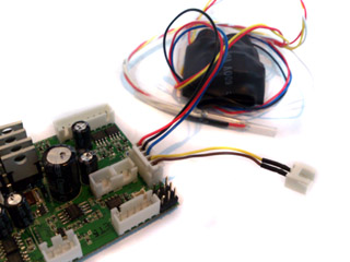
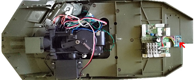
Disconnect RX-18 and plug cables to the same connector on TK board,
Set
Sound Volume to middle
Install
a switch cable (for example, HL Smoke Unit Switch Cable)
to SW connector( Switch Cable Port)
as power switch.
Because HL tank already have power switch on battery cable path, so additional
switch is not required, just to use a jumper to short
pins in SW Cable port or connect a switch cable and keep it switched on.
When high current track motors are used, such as 400/480 motor,
power switch on battery cable path will not be able to handle,
connect a switch cable (for example, HL Smoke Unit Switch Cable)
to this port
as power switch.
(Optional). wire a 2.2 ohm
1/2W (color code: red read gold gold) in-serial resistor to turret rotate, elevation and airsoft motor
to limit the current to protect FETs in case motor stall occured.
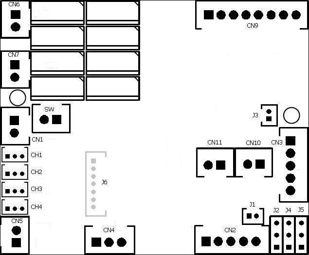
Connect
channel cables to receiver according to RC
mode( See picture "TK series connector and pin assignments" ) . if you are not sure what mode you RC system is, just swap CH2 and CH3 and
try again.
TK40 board has BEC( Battery
eliminate
circuit),
can power receiver through channel cables, no additional battery is needed for
receiver
Set CH1,
2 and 3 trimmer on transmitter to center position, Set CH4 trimmer on
transmitter to most left or right position,
Connect power adaptor( See FAQ )
Switch on TK board and transmitter, you should hear
turret traverse
sound. if not, please contact us.
gently
move CH4(Multi
function control signal 2)
trimmer to center till
turret traverse is gone.
gently
move CH2(Throttle )
trimmer up and down if you hear motor hum sound.
Cannon
firing sound should be generated and
recoil servo should moves when move
CH3 stick to most top position, if not, gently move CH3(Multi
function control signal 2 )
trimmer up and down till
it work correctly.
You are
all set
Disconnect power adaptor and connect battery( make sure that battery is fully
charged).
Installation Video Guide on Internet:
https://www.youtube.com/watch?v=_eIRTIMyl2g
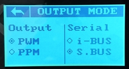
Flysky i6s setup
Transmitter:
1.Turn on Transmitter i6s and enter setting
function, go to system->output mode, than set Serial to S.BUS
2. Enter aux channel setup, set
channel 5 to SwA, channel 6 to SwD, channel 7 to SwB, channel 8 to SwC, channel
9 to VrA and channel 10 to VrB
3. Go to system->stick mode, then set to M1 mode
4. Go to end points page, set end point to
100% for every channel.
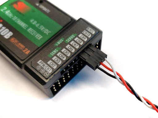
Receiver and control board:
1. Plug connector with S.BUS
label on it into S.BUS port on receiver.
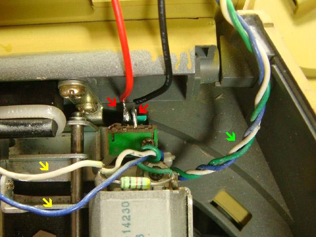
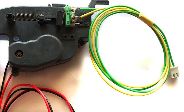
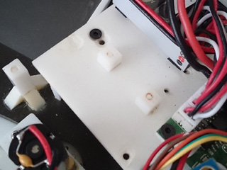
RecoilUnit Installation
TAMIYA recoil unit
installation( set Upper Hull Functions
(CN9) Mode:to
TAMIYA RECOIL MODE )
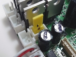
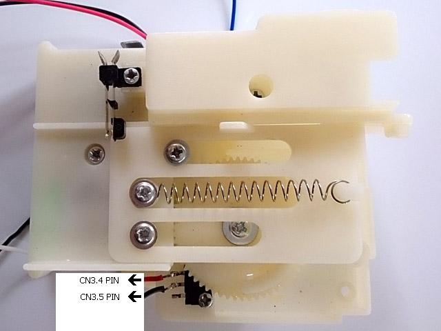
STEP1.
disconnect white and blue wire from recoil unit switch( see arrow in yellow),
add cable connector to recoil switch( see arrow in red ), left green-white-blue cable
not touched ( see arrow in green)
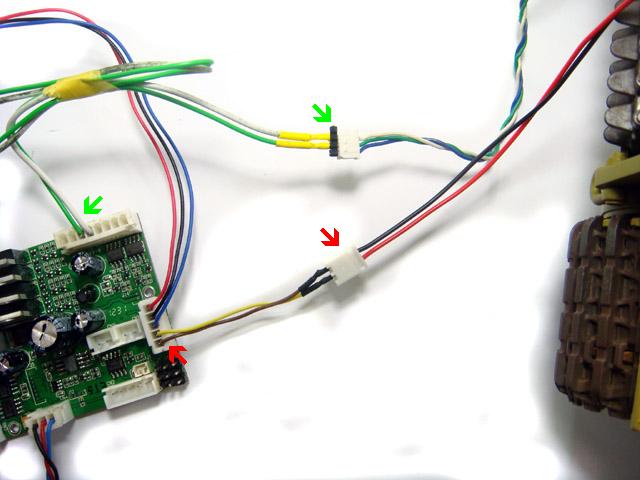
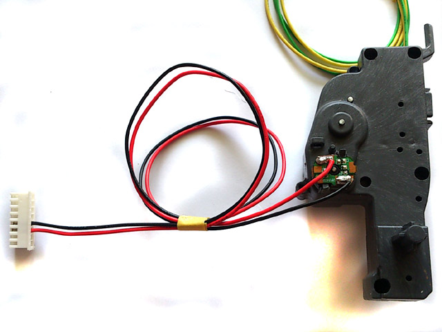
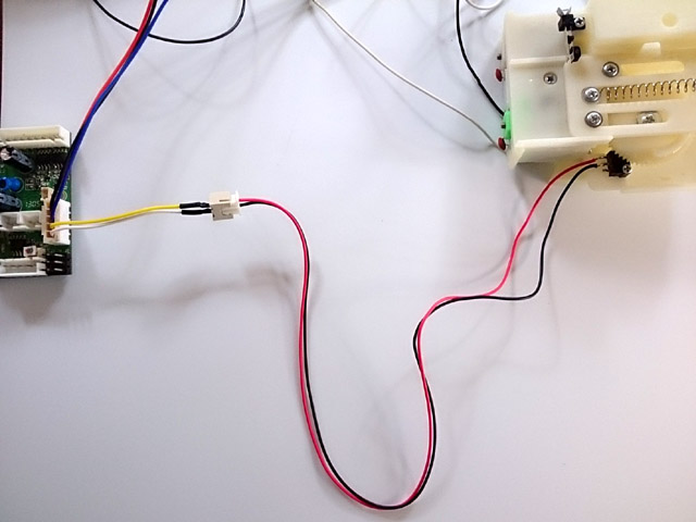
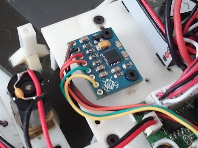
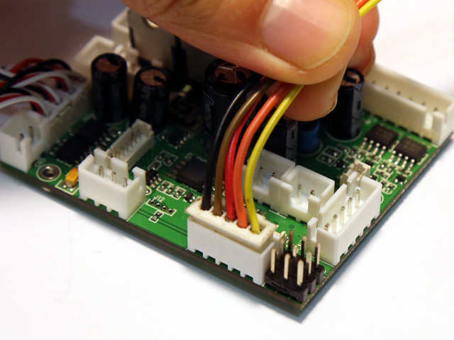
STEP2. green wire and white wire in
green-white-blue cable goes to 3rd pin on CN9 and 4th pin on CN9(see arrow in
green), black and red wire in red-black cable goes to 4th and 5th pin on CN3(see
arrow in red).
HLrecoil unit
installation:
STEP1.
Set Upper Hull Functions
(CN9) Mode:
to
HL Recoil MODE,
STEP2.
Connect detection SW( Pressed-to-Short type ) to 4th and 5th pin on CN3 or via
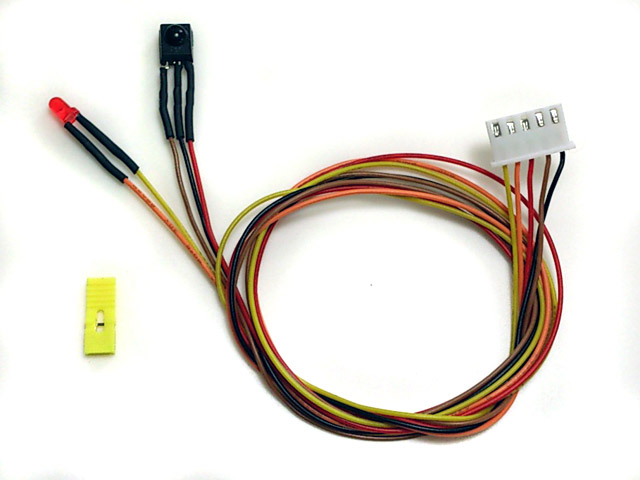
the plug (Yellow and brown wire) from HL HIGH-TENSION FLASHER. Latest
released HL recoil unit already has detection switch on it.
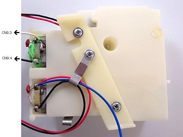
STEP3.
connect motor - to 4th pin on CN9.connect motor + to 3rd pin on CN9.
Asiatam recoil unit
installation:
STEP1.
Set Upper Hull Functions
(CN9) Mode:
to
Asiatam Recoil Mode
STEP2.
Connect Recoil motor + to 3rd pin on CN9.connect motor - to 4th pin
on CN9.
STEP2.
Connect detection SW to 4th and 5th pin on CN3 or via the plug (Yellow and
brown wire) from HL HIGH-TENSION FLASHER
Gun Barrel Stabilizer(GBS)
overview and installation
GBS is an
optional module of TK60. When GBS is turned on, it
detects the tank movement and
compensate gunrotation and elevation
to stabilize the gun automatically.
When GBS is turned on, operator can still change gun elevation and direction
under GBS compensation, GBS have the following features:
-
2-axis gun stabilization in turret rotation and gun
elevation.
-
Fully programmable gun elevation
real angle calculator allows GBS to work with different elevation
setup
,
- Fully programmable turret motor
controller allows GBS to work with different motor/gear box
setup,
- Auto reload position, Gun barrel goes to to
reload position after fire, and return to last position when reload when reload
time expired,
-
Adjustable
Engine deck level,
-
Adjustable auto reload position,
-
Gun barrel momentum effect,
- GBS
unit d
imensions: 20 x
16 x 3mm.
Servo for GBS -
-Control System: +Pulse Width Control 1520usec
Neutral
-Required Pulse: 3-5 Volt Peak to Peak Square Wave
-Operating Voltage: 4.8-6.0 Volts
-Operating Angle: 45 Deg. one side
Power on GBS
calibration -
When power
on TK60G2, GBSstarts a reset
process and must be kept stationary.
Head Light LEDis turned ON during
GBS calibration and you must
not to move the tank during
calibration. The
GBS are very sensitive and you should nottouch or vibrate the GBS during power on reset. The process will take
around 2 seconds. Head Light LED will
be turned off when
calibrationcompleted.
An in-series 200-ohm resistor is needed for GBS LED
Mounting of GBS
-
The GBSunit must be mounted securely and
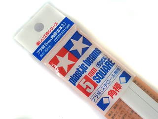
horizontally on the turret, here is an example, first
to use Tamiya 5mm square beam, cut into 5~6mm in length, make 1.6mm hole, then
glue to turret floor by cement
Bolt GBS unit with the screws came with GBS unit, and plug
connector to J6 port on TK60G2, Length of GBS cable can
not exceed 80mm or TK60G2 may miss reading GBS.
For
accurate motion detection, it must be kept
within 5 degree with turret base plate.
mounting directions is as
shown in following picture. Servo
for elevation is Futaba S3003 in this
setup.
Recommended GBS mounting position for Leopard 2
Turning GBS
on/off -
GBS
can be turned on/off byGun Barrel
Stabilizer on/off commanded,
you can also hear click sound when turn it on and off
Adjusting gun elevation angle -
The gun elevation
V gain setting is used to adjust the
amount of
gun elevation servo angle
to meet different mechanical setup. adjusting
procedures
are
-First to put TK60G board in IR programming mode.
-Turn
GBS on and moves the gun
barrel
to horizontal position.
-Tilt the tank for 15-20
degree.
-Use IR configure remote to
adjustservo gain value until the gun is
horizontal again.
-Power off TK60G board, remove
jumper and turn power again to leave
IR programming mode.
Adjusting gun elevation angle
calculator gains -
The angle
calculator's fast gain and slow gain settingsare used to adjust the
angle calculation, adjusting procedures are
-First to put TK60G2 board in IR programming mode.
-Turn
GBS on and moves the gun
barrel
to horizontal position.
-Tilt the tank for 10-20
degree.
-Rotate turret in various speed
( from low to full speed), if elevation speed is too slow, increase slow gain a
bit, otherwise, reduce slow gain,
-rotate turret to 12 o'clock position,
tilt the tank
hull about 15-20
degree in various speed,if
elevation speed is too slow, can not keep up tank hull
tilt speed, increase fast gain a bit, if elevation moves faster the hull tile
speed and over the position it should be (overshoot), decrease fast gain a bit
-Power off TK60G2 board, remove
jumper and turn power again to leave
IR programming mode.
Adjusting
turret rotation motor control gains -Turret
rotation motor P , I and D gainare used to
meet the characteristic of turret rotate motor and design on your tank. adjusting procedures are as the following.
-First to put TK60G2 board in IR programming mode.
-Turn GSU on
-Rotate
tank hull from stationary
to low speed, if turret motor does not start as quick as tank hull rotation, increase
I gain a bit, if turret motor runs too fast (overshoot) , decrease I
gain a bit.
-Rotate
tank hull in various speed( low,
middle and full) , if turret rotation speed is too slow, can't keep up hull
rotation, increase P gain, otherwise, reduce speed gain,
-Stop
tank hull rotation from various
speed, if turret stops too early, decrease D gain, if turret stops too late
increase D gain.
Tank
Personalization
坦克個人化設定
Settings
of TK series board can be changed by
a IR configuration remote
as IR command transmitter, and TAMIYA battle unit(TBU),
Heng-Leog battle
unit(HBU), or our IR configuration line as IR command receiver.
STEP 1: Turn power off, Turn power off, Turn power off,
步驟1:
關閉控制器電源
STEP 2: Plug programming line/TBU
through TBU/HBU base into
CN2 Infrared Port
,
步驟2:
接上紅外設定接收線/田宮對戰器到CN2接口
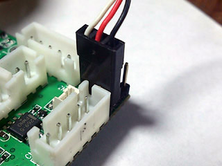
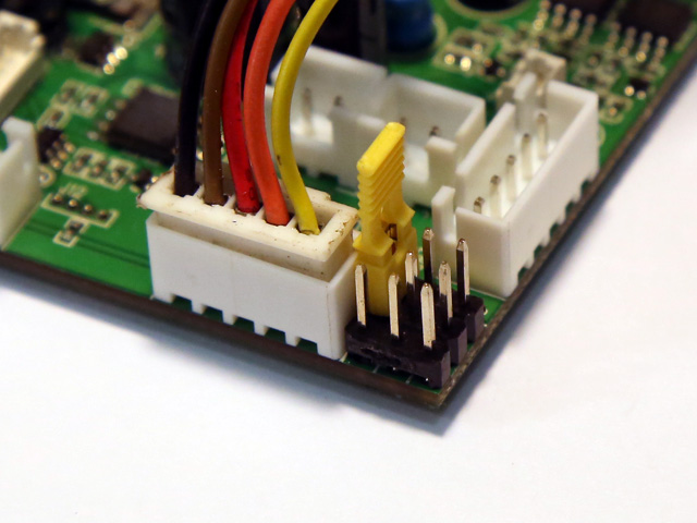
STEP 3: Install a jumper to J2
as shown below, Turn power on,
步驟3:
將跳接器插上J2,打開電源
STEP 4:Refer to function table listed below,
point
IR configuration remote to
TBU/HBU/Programming line receiver, and press the
button
of setting that you want to change,
"*"
sign in
function table means
the default setting that is programmed in factory
Note:
Suggested Value, can be changed by Reload Time and
Invulnerability time setting function
註: 建議值,
可以透過裝填時間及無損害時間設定修改
Save
current setting to
PRESET 1: Press number
key "1" on IR Configuration Remote to save,
將目前設置儲存到預設值1: 按紅外發射器上數字健"1"
Available Settings
選項
Indicator
flashes times
指示燈閃爍次數
Description
描述
Save to PRESET 1
1
Indicator flashes when setting
is saved
Save
current setting to PRESET 2: Press number
key "2" on IR Configuration Remote to save,
將目前設置儲存到預設值2: 按紅外發射器上數字健"2"
Available Settings
選項
Indicator
flashes times
指示燈閃爍次數
Description
描述
Save to PRESET 2
2
Indicator flashes when setting
is saved
*Once
you've adjusted everything, you can
push "1" or
"2" to save
current setting to PRESET 1
or 2. If you don't do this saving the board remembers
the last settings.
Use saved settings:
Press "ENT" or "SOUND MODE" Key on
IR Configuration Remote to select.
載入預設值:
按紅外發射器上"ENT"或""SOUND
MODE"
Available Settings
選項
Indicator
flashes times
指示燈閃爍次數
Description
描述
Use PRESET 1
setting
使用預設值1
1
UsePRESET 2 setting
使用預設值2
2
Use Factory Default Setting
( Read-Only )
使用出廠預設值
3
To
restore factory
default value in case of setting data is messed up.
當設置混亂時回復出廠值
*To
switch between the presets you press either "sound
mode" or "enter" button, once the preset is selected,
switch tank off and remove setup jumper. Switch back on and away you
go.
*載入預設值後需重新開關電源使控制器運行在新的設定值下
Mixer Mode:
Press
(MUTE) key on IR Configuration Remote to select( TK50HS, TK50HSP ).
混控模式:按紅外發射器上
(靜音)鍵(
TK50HS, TK50HSP
).
Available Settings
選項
Indicator flashes times
指示燈閃爍次數
Description
描述
Mixer Mode
1
混控模式1
1*
Tank mode 1
坦克模式1
CH1 controls
rudder, CH2
controls throttle.
CH1控制方向, CH2控制油門
Proportional steering,
sharp and pivot turn* are supported
支持比例轉向, 原地迴轉, 超原地迴轉
Left Track
左履帶
Right Track
Pivot
Turn
超原地迴轉
Sharp
Turn
原地迴轉
Proportional
Steering
比例轉向
Proportional
Steering
比例轉向
Sharp
Turn
原地迴轉
Pivot
Turn
超原地迴轉
Mixer Mode
2
混控模式2
2
OFF mode
關閉模式
CH1
controls left track, CH2 controls right track
CH1左履帶,
CH2控制右履帶
When
using triple differential gear box,
當使用三差速齒輪箱時
CH1
controls steering motor(CN6),
CH1控制迴轉用馬達(CN6)
CH2
controls propulsion motor(CN7)
CH2控制推進用馬達(CN7)
Mixer Mode
3
混控模式3
3
Triple
differential gear box simulation
mode
模擬三差速模式
(World of
Tank Mode )
(坦克世界模式)
CH1 controls
rudder, CH2
controls throttle.
CH1控制方向,
CH2控制油門
Left
track speed = Throttle - rudder
左履帶速度 =
油門
- 方向
Right
track speed = Throttle + rudder
右履帶速度 =
油門
+ 方向
Mixer Mode4
混控模式4
4
Tank mode 2
坦克模式1
CH1 controls
rudder, CH2
controls throttle,
CH1控制方向, CH2控制油門
Proportional steering and
sharp turn are supported
支持比例轉向, 原地迴轉
Left Track
左履帶
Right Track
0%
Turn
原地迴轉
Proportional
Steering
比例轉向
Proportional
Steering
比例轉向
0%
Turn
原地迴轉
Mixer Mode
5
混控模式5
5
Half-Track mode 1
半履帶車模式1
CH1 controls
rudder, CH2
controls throttle,
CH1控制方向, CH2控制油門
Left Track
左履帶
Right Track
50%
Turn
50%
迴轉
Proportional
Steering
比例轉向
Proportional
Steering
比例轉向
50%
Turn
50%
迴轉
Mixer Mode
6
混控模式6
6
Half-Track mode 2
半履帶車模式2
CH1 controls
rudder, CH2
controls throttle,
CH1控制方向, CH2控制油門
Left Track
左履帶
Right Track
75%
Turn
75%
迴轉
Proportional
Steering
比例轉向
Proportional
Steering
比例轉向
75%
Turn
75%
迴轉
Mixer Mode
7
混控模式7
7
NA,Do not select this mode
未使用, 請勿選
Mixer Mode
8
混控模式8
8
NA,Do not select this mode
未使用, 請勿選
Mixer Mode:
Press
(MUTE) key on IR Configuration Remote to select( S.BUS GBS version: TK40SPG2 )
混控模式:按紅外發射器上
(靜音)鍵(
TK50HSPG2 ).
Available Settings
選項
Indicator flashes times
指示燈閃爍次數
Description
描述
Mixer Mode
1
混控模式1
1*
Tank mode 1
坦克模式1
CH1 controls
rudder, CH2
controls throttle.
CH1控制方向, CH2控制油門
Proportional steering,
sharp and pivot turn* are supported
支持比例轉向, 原地迴轉, 超原地迴轉
Left Track
Right Track
Pivot
Turn
超原地迴轉
Sharp
Turn
原地迴轉
Proportional
Steering
比例轉向
Proportional
Steering
比例轉向
Sharp
Turn
原地迴轉
Pivot
Turn
超原地迴轉
Mixer Mode
2
混控模式2
2
OFF mode
關閉模式
CH1
controls left track, CH2 controls right track
CH1左履帶,
CH2控制右履帶
When
using triple differential gear box,
當使用三差速齒輪箱時
CH1
controls steering motor(CN6),
CH1控制迴轉用馬達(CN6)
CH2
controls propulsion motor(CN7)
CH2控制推進用馬達(CN7)
Mixer Mode
3
混控模式3
3
Triple
differential gear box simulation
mode
模擬三差速模式
(World of
Tank Mode )
(坦克世界模式)
CH1 controls
rudder, CH2
controls throttle.
CH1控制方向,
CH2控制油門
Left
track speed = Throttle - rudder
左履帶速度 =
油門
- 方向
Right
track speed = Throttle + rudder
右履帶速度 =
油門
+ 方向
Mixer Mode4
4
NA,Do not select this mode
未使用, 請勿選
Mixer Mode5
5
NA,Do not select this mode
未使用, 請勿選
Mixer Mode6
6
NA,Do not select this mode
未使用, 請勿選
Mixer Mode7
7
NA,Do not select this mode
未使用, 請勿選
Mixer Mode8
8
NA,Do not select this mode
未使用, 請勿選
Upper Hull Functions
(CN9) Mode:
Press
"POWER" key
on IR Configuration Remote to select
上車體功能模式:
按紅外發射器上"電源"鍵
Note:
Available Setting is ALWAYS from TAMIYA Recoil MODE when power is
applied, then go to HL Airsoft Mode( indicator flashes 2 times) when
POWER key is pressed first time,
It does not means that the selected setting before power off is not saved.
Armor type:
press number
key "9" on IR
Configuration Remote to select
裝甲種類按紅外發射器上"9"
鍵
Available Settings
選項
Indicator
flashes times
指示燈閃爍次數
Description
說明
Heavy Armor
重型
1*
Resistance to machine gun
能抵抗機槍射擊,
不會有毀損
Soft
skin, like Trucks
輕型
2
No resistance to machine gun
不能抵抗機槍射擊,會有毀損
Sending IR code when firing
machine gun:
press number
key "6" on IR
Configuration Remote to select
機槍射擊時發送機槍紅外信號
按紅外發射器上"6"
鍵
Available Settings
選項
Indicator
flashes times
指示燈閃爍次數
Description
說明
Not
to send
MG
IR code
不發送
1*
To send MG IR code
發送
2
Primary weapon reload time:
press number
key "4" on IR
Configuration Remote to select
主砲裝填時間按紅外發射器上"4"
鍵
Available Settings
選項
Indicator
flashes times
指示燈閃爍次數
Description
說明
2 seconds
3秒
2*
3 seconds
3秒
3
4 seconds
4秒
4
5 seconds
5秒
5
6 seconds
6秒
6
7 seconds
7秒
7
8 seconds
8秒
8
9 seconds
9秒
9
10
seconds
10秒
10
11 seconds
11秒
11
12
seconds
12秒
12
13
seconds
13秒
13
14
seconds
14秒
14
15
seconds
15秒
15
Rounds of Primary weapon:
press number
key "8" on IR
Configuration Remote to select
主武器彈藥數按紅外發射器上"8"
鍵
Available Settings
選項
Indicator
flashes times
指示燈閃爍次數
Description
說明
Not
limited
無限
1*
8 rounds
8發
2
16 rounds
16發
3
24 rounds
24發
4
32 rounds
32發
5
40 rounds
40發
6
48 rounds
48發
7
56 rounds
56發
8
64 rounds
64發
9
72 rounds
72發
10
80 rounds
80發
11
88 rounds
88發
12
96 rounds
96發
13
104 rounds
104發
14
112
rounds
112發
15
120
rounds
120發
16
Primary weapon
IR code:
press number key "0" on
IR Configuration Remote to select
主武器紅外碼按紅外發射器上"0"
鍵
Available Settings
選項
Indicator
flashes times
指示燈閃爍次數
Description
說明
TAMIYA cannon code
田宮主砲碼
1*
For TAMIYA IR battle
田宮對戰用
HL cannon code
HL主砲碼
2
For HL IR battle
HL對戰用
Repair code
修復碼
3
For Bergepanzer
application,
damage count decreased by 1 when this IR
code is received, each repair needs 15s, no other vehicle
can damage vehicle that is under this mode
救援車輛用.
每接收到此碼一次, 生命值回復1.
Machine Gun code
機槍
4
Vehicle
with MG
配備機槍的載具
Invulnerability time:
Vehicle is Invulnerable during
this period,
press number
key "7" on IR
Configuration Remote to select
無損害時間:
按紅外發射器上"7"
鍵
Available Settings
選項
Indicator
flashes times
指示燈閃爍次數
Description
說明
Vehicle can not be recovered from destroyed mode
不會自擊毀狀態回復
1
1 second
1秒
2
2 seconds
2秒
3
3 seconds
3秒
4
4 seconds
4秒
5
5 seconds
5秒
6
6 seconds
6秒
7
7 seconds
7秒
8
8 seconds
8秒
9
9 seconds
9秒
10
10
seconds
10秒
11*
TAMIYA
Heavy tank
田宮重型坦克
11
seconds
11秒
12
12
seconds
12秒
13
TAMIYA
Medium tank
田宮中型坦克
13
seconds
13秒
14
14
seconds
14秒
15
TAMIYA
Light tank
田宮輕型坦克
15
seconds
15秒
16
Max hit can take:
Press number key "5"
on IR Configuration Remote to select
最大被彈數按紅外發射器上"5"
鍵
Available Settings
選項
Indicator
flashes times
指示燈閃爍次數
Description
說明
1 round
1發
1
2 rounds
2發
2
3 rounds
3發
3
TAMIYA
Light tank
田宮輕型坦克
4 rounds
4發
4
5 rounds
5發
5
6 rounds
6發
6
TAMIYA
Medium tank
田宮中型坦克
7 rounds
7發
7
8 rounds
8發
8
9 rounds
9發
9*
TAMIYA
Heavy tank
田宮輕型坦克
10
rounds
10發
10
11
rounds
11發
11
12
rounds
12發
12
13
rounds
13發
13
14
rounds
14發
14
15
rounds
15發
15
Function Page Selection:
Press "-/--" Key on IR Configuration Remote to
select.
Available Settings
選項
Indicator
flashes times
指示燈閃爍次數
Description
說明
Select
settings on Page 1
1*
TK board
goes back to this page after power on
Select settings on Page 2
2
Select settings on Page 3
3
Select settings on Page 4
4
*Text in black means that
setting function is on page1.
Function Page 2
Gun elevation EPM (EPM1) Mode:
press "
1"key
on IR configuration remote to select
Available Settings
Indicator
flashes times
指示燈閃爍次數
Description
說明
ESC Mode
1*
ESC1 enabled, PWM1
disabled
PWM Mode
2
ESC1 disabled, PWM1
enabled
*A Power on and off cycle( turn off power for
5 seconds then power on) is needed to active change after mode change.
Gun elevation servo( PWM1) Direction:
press "
2"key
on TV remote to select
Available Settings
Indicator
flashes times
指示燈閃爍次數
Description
說明
Normal
1*
Reversed
2
Turret rotation/gun traverse EPM(EPM2) Mode:
press "
3"key
on IR configuration to select
Available Settings
Indicator
flashes times
指示燈閃爍次數
Description
說明
ESC Mode
1*
ESC2 enabled, PWM2
disabled
PWM Mode
2
ESC2 disabled, PWM2
enabled
*A Power on and off cycle( turn off power for
5 seconds then power on) is needed to active change after mode change.
Turret rotation servo (PWM2) Direction:
press "
4"key
on IR configuration to select
Available Settings
Indicator
flashes times
指示燈閃爍次數
Description
說明
Normal
1*
Reversed
2
Low Battery threshold :
press "
0"key
on IR configuration remote to select, when detected battery voltage lower than
setting, ESC output will be reduced.
Available Settings
Indicator
flashes times
指示燈閃爍次數
Description/Battery Type
說明/電池種類
Reserved
1
6V
2
Li-Ion 2S 7.4V
Li-Po 2S 7.4V
Li-Fe 2S
6.6V
Ni-Cd 6S 7.2V
Ni-Mh 6S 7.2V
6.4V
3*
Li-Ion 2S 7.4V
Li-Po 2S 7.4V
Li-Fe 2S 6.6V
Ni-Cd 8S 8.4V
Ni-Mh 6S 7.2V
6.8V
4
Li-Ion 2S 7.4V
Li-Po 2S 7.4V
7.5V
5
Li-Ion 3S 11.1V
8V
6
Ni-Mh 8S 8.4V
9V
7
Li-Po 3S 11.1V
Reserved
8
Engine Sound Throttle input select:
press "
SOUND MODE"key
on IR configuration remote to select
Available Settings
Indicator
flashes times
指示燈閃爍次數
Description
說明
CH2
1*
Engine sound module
only refer to CH2
CH1 and CH2
2
Engine sound module
refer to CH1 and CH2
Ultrasonic ESC1 (CN6) input select:
press "CH
UP"key
on IR configuration remote to select
Available Settings
Indicator
flashes times
指示燈閃爍次數
Description
說明
CH1
1*
When mixer is set to
OFF mode
CH1
controls steering motor(CN6)
CH2
controls propulsion motor(CN7)
CH2
2
When mixer is set to
OFF mode
CH2
controls both steering motor(CN6)
propulsion motor(CN7)
Can be used in twin motor
application, such as truck
Firing
tank gun hullrecoilOn/Off: Press "POWER"
on IR Configuration Remote to select
主砲射擊被時車體振動開/關按紅外發射器上POWER鍵
Available Settings
選項
Indicator
flashes times
指示燈閃爍次數
Description
說明
On
開啟
1*
Off
關閉
2
Use saved settings:
Press "MUTE Key on IR Configuration Remote to select.
Available Settings
Indicator
flashes times
指示燈閃爍次數
Description
說明
Use PRESET 1
setting
1
UsePRESET 2 setting
2
Use Factory Default Setting
( Read-Only )
3
To
restore factory
default value in case of setting data is messed up.
*To
switch between the presets you press either "sound
mode" or "enter" button, once the preset is selected,
switch tank off and remove setup jumper. Switch back on and away you
go.
Software Version:
press
"(?)","DISPLAY"
or "DRC-MF" key on
IR Configuration Remote to
select.
Version number
Indicator
flashes times
指示燈閃爍次數
Description
說明
Version 1
1*
Version 2
2
:
:
Function Page 3
Ultrasonic ESC
start voltage increase:
Select page 3, press
"3" on IR Configuration Remote to increase level,
indicator flash once each time, indicator flash twice when reach maximum level
Ultrasonic ESC
start voltage decrease:
Select page 3 , press
"6" on IR Configuration Remote to decrease level,
indicator flash once each time, indicator flash twice when reach minimun level
Ultrasonic ESC start voltage reset to zero:Select page 3, press
"DISPLAY" or "?" Key on IR
Configuration Remote to reset start voltage,
indicator flash once every time.
Status read out and IR battle test by IR
configuration remote
Point
Configuration IR remote to TBU/HBU and press key listed below to show
vehicle status or test IR battle function.
No jumper should be installed on J1.
KEY on SONY IR
Configuration Remote
Description
Number Key "1"
To repair vehicle,
damage count decreased by 1
Number Key "2"
Fire
cannon to
vehicle
Number Key "3"
Fire machine gun to
vehicle
Number Key "4"
Number of flash indicate
remain hits
can take
FAQ
Q:My TK board can not
register a hit from Tamiya tank.
A:
To check "Receive Tamiya IR code" setting. TK board won't
response Tamiay IR code when this setting is disabled.
Q:
The airsoft motor does not run until after the gun fire sound has played and the
reload sound has happened. I want the airsoft motor to run while the gun sound
plays. I also planned to make recoil work with the airsoft but when I fire the
gun, the recoil servo operates in time to the sound but has returned to the
normal position when the airsoft motor operates. A:Just need to set Main Gun Function Mode to AirSoft mode, then
cannon sound, servo recoil and airsoft unit will be synchronized.
Q:I already set Main
Gun Function Mode to HL AirSoft MODE, but
AirSoft motor does not run when
I give fire cannon command.
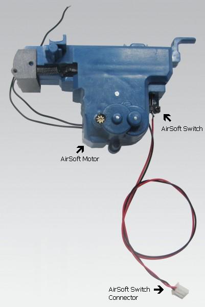
Q:
Airsoft unit fires continuously and have no cannon sound.
A:When main Main Gun
Function Mode is configured to AirSoft
Mode, TK board start to drive AirSoft motor (thought CN9 3rd &4th pin) when fire
cannon command is received.
when Airsoft just fired, Airsoft switch is closed , TK board knows it thought CN3 Pin4
& Pin5.
and then stop to drive Airsoft Motor and start to generate cannon. So in order
to make it works properly, AirSoft motor need to be connected to CN9 pin3
and pin4. AirSoft switch connector to CN3 Pin4
& Pin5.
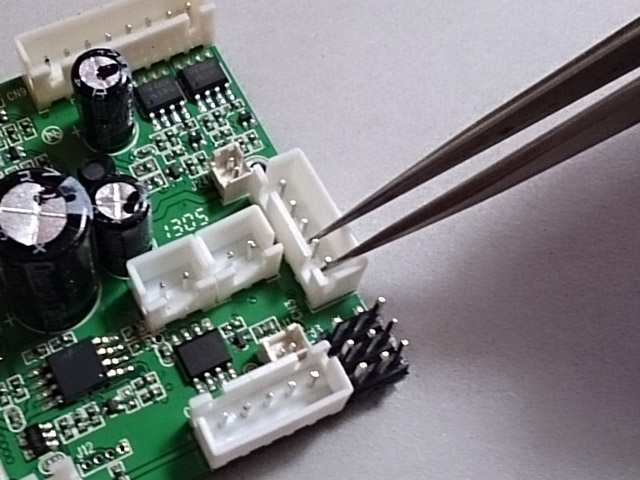
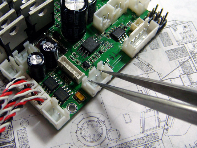
You can
simply test it by a
tweezers, to short and release
it will stop AirSoft motor.
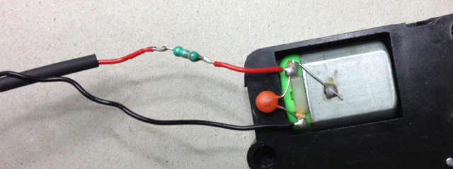
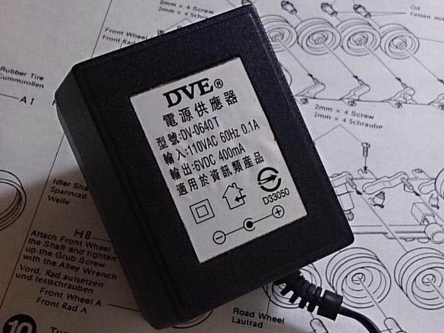
Q:
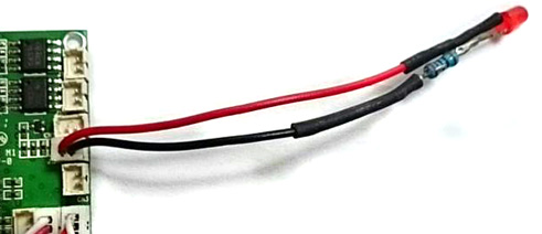
How to avoid damage that caused by short circuit to the board? A:Damage can be prevented by using a current limited power
adaptor as power source, first to find a ~6V, 400mAh power adaptor, 1K 1/4W ohm
resistor, LED and a motor cable(from HL cable Set)
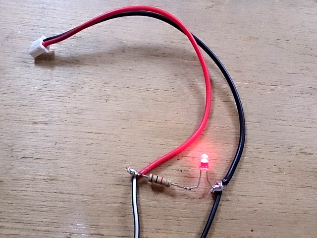
then
connect + wire(with white strip) from adaptor to red wire of HL cable, - wire to
black wire of HL cable, adn wire resistor and LED as the following to act as
indicator.
Each
time, when you did some modification on circuit or after installation, use this
as power source fist. plug connect each by each, and LED will be dimmed
immediately if any shortage in circuitry and not thing on TK board will be
damaged because power can only supply low & limited current.
The
board might be act very strange when it's power by this, such as motor can not
moves will, cannon fired unexpectedly when turret rotation sound comes up, these
are quite normal because current is not enough.
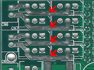
Q:
When I move left stick backward, only the right track goes backward the left
track does not move, It is possible I crossed the +positive and --negative
terminals when connecting the new motors? A:
Yes, when +positive and --negative
terminals are crossed, one of terminal will burn out immediately, you can bend
FETs a little bit to check these traces, one of them should be broken. you can
reconnect it by soldering to fix the problem.
We recommend that to use power adapter(7.2V, 400mAh) as power
source after rewiring. then switch to battery when everything are tested OK.
Q: Tank hull
recoil movement direction is not correct, moves forward and then backward while
firing main gun. A: Just need to swap motor cables, CN6 to Motor
Right, CN7 to Motor Left, and turn on servo reverser function on throttle
channel from radio transmitter.
Q: All function runs but just no sound!!
A:
This can be the
common issue on HL Volume Control
board, just to short outer pins of CN4 with
tweezers to verify it. if
sound comes out when doing this, the HL volume control board is broken.
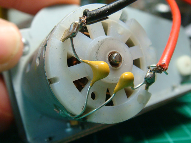
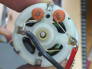
Q: Do I need noise filtering capacitor on motor
A:
Yes, it's needed to prevent back EMF to interference TK20 board. All HL stock
tank already have it on motors
This type of capacitor is not good, DO NOT USE!
Q: What's the IR battle range of TK20
A:
The table below shows the test
result we've done here or from customer site,
IR Transmitter
IR Receiver
Board Version
Test result
Test environment
HL
Original IR LED
HL Battle
Unit
TK20/22/40/50/60/80
13M
Outdoor
IR010
TAMIYA Battle Unit
TK20/22/40/50/60/80
>30M
Outdoor
Q:Tank
moves backward faster than forwards and does not turn. It only turn if firstly
turn steering stick and secondly throttle stick.
A: To turn off mixer on transmitter and test
again.
Q:Can get motor
sounds, cannon sounds, turret sounds, but no motion on either drive motors or
turret rotation gearbox
A: Check if battery voltage
is too low, auto cutoff function cuts motor off when battery voltage is too low.
Q: What
is
Mixer
A: A piece of software
that convertsRudder and
Throttlecontrol signalto Left and
Right track speed signal. All TK board has mixer on it, mixer
function on RC transmitter need to be turned off.
Q:What is Safety shutoff:
A:
Controller cuts motor off and waits signal come back.
Q:What is Auto cutoff:
A:The motor cutoff will
occurred when battery input drops below minimum supply voltage of controller.
Q: Which RC system can works
with TK board:
A:Basically, TK can work with all kind of aftermarket RC system
as long as it's PWM system, here is a table list most popular one.
Brand
Band
Model Number
Result
Futaba
72M
T4VF
OK
Futaba
27M AM
4WD
OK
Futaba
2.4G
T4YF-2.4G
OK
TURNIGY
2.4G
9X
OK
Spektrum
2.4G
OK
PLANET
2.4G
OK
FlySky
2.4G
FS-CT6B
OK
( Need
to turn mixer function on transmitter off )
Hobby
King
2.4G
HK T6A
OK
Perfex
2.4G
M24-H radio
OK
Tactic
TTX
TTXseries
OK
JR
27M
OK
Q: Audio Amp thermal
protection:
A:
that turns off device when junction temperature over 150 degree C to prevent
damage
Q:
Is it possible to make additional settings using
existing IR signalsfor example to make
HL IR
signal and 9 hits can take, originally 5 hits?
A:
yes, IR code to receive, IR code to transmit, preset
& battle data can be set
independently.
Q:
Is it possible to set setting with other device
(not SONY IR code remote)?
A:Only Sony IR code remote can be used, you can also
have universal remote and configure it to SONY mode.
Q:Any Other
SONY remote, such as SONY Bravia unified IR
Configuration Remote, can config TK20? A:
Can't sure, with more and more
setting function are added, some code not common on every remote are used. so we
suggest to use same remote as we use.
Q: What's BEC
A:BEC stands for
battery elimination circuit. This circuit powers the
receiver thought channel cable, no
secondarybattery source is required.
Precaution
Use dry battery or power supply as
power source at testing to keep burn down anything if any error on modification.
then use chargeable battery when every function working normally.
Read
carefully and fully understand the instructions before commencing assembly.