Turn
your favorite 1/35 static tank model into
R/C with proportional radio control and great sound!!!
(specifications
and design are subject to change without notice)
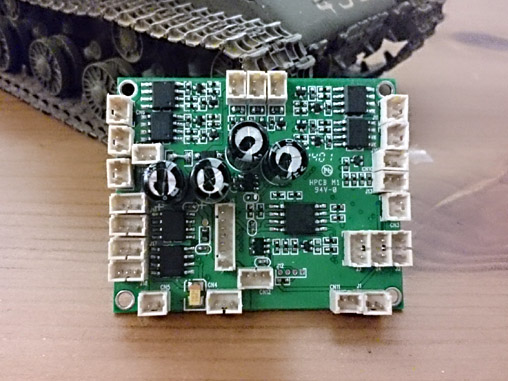
Overview
TK30 series controller uses 4
channels RC system to control R/C tank's forward/backward movement, sharp
turning, pivoting, turret rotation and gun barrel evaluation at variable speed 7A track motor driver
22KHz, 8-bit high quality sound with digital sound mixer
Maximum of 5 channel of sound track, main gun,
machine gun, turret rotate, gun barrel elevation and engine sound can be
generated at the same time
3W
sound output power
0.8A BEC
Support TAMIYA 1/16, TAMIYA 1/35,
HengLong and VStank IR
battle
Support
RealRecoil servo port Safety shutoff prevents
unwanted movement while signal lost
Auto R/C signal detection Miniature design(49mm X
39mm X 10mm) for 1/35 R/C Tank
Terminology
Ultrasonic
ESC is the ESC block which switch FET at ultrasonic speed, make motor
rotation very smooth and quite.
RealRecoil
allows you to recreate real gun barrel recoil movement with single & cheap servo
motor
V2 Smoker driver smoker fan/compressor speed is proportional to
engine RPM and Load
Variants
TK35
TK35G2
TK37
TK37G2
TK37S
TK37SG2
Remote Control System
Traditional 4-CH AM, FM or 2.4G RC system
Traditional 4-CH AM, FM or 2.4G RC system
Traditional 4-CH AM, FM or 2.4G RC system
Traditional 4-CH AM, FM or 2.4G RC system
2.4G RC system
with
S.BUS
2.4G RC system
with
S.BUS
Control
Scheme
4-CH
4-CH
4-CH
4-CH
10-CH
10-CH
User software Programmability
NO
NO
YES
YES
YES
YES
User Sound
Programmability
NO
NO
YES
YES
YES
YES
User Tank Personalization
Programmability
NO
NO
YES
YES
YES
YES
TAMIYA 1/16 IR battle
Compatible
YES
YES
YES
YES
YES
YES
TAMIYA 1/35 IR battle
Compatible
YES
YES
YES
YES
YES
YES
HL IR battle
Compatible
YES
YES
YES
YES
YES
YES
VSTANK IR battle
Compatible
YES
YES
YES
YES
YES
YES
Damage Simulation on track
YES
YES
YES
YES
YES
YES
Damage Simulation
on
turret
rotation and gun elevation
YES
YES
YES
YES
YES
YES
Sound set for specific tank model
YES
YES
YES
YES
YES
YES
Engine Sound
Simulation
V1
V1
V2
V2
V2
V2
Track driver Current
7A
7A
7A
7A
7A
7A
Track driver Momentum Effect
with ON/Off Control
YES
YES
YES
YES
YES
YES
Turret Rotation Speed Control
YES
YES
YES
YES
YES
YES
Gun Elevation Speed Control
YES
YES
YES
YES
YES
YES
Gun Elevation
Servo Port
YES
YES
YES
YES
YES
YES
Gun/Turret Rotate
Servo Port
YES
YES
YES
YES
YES
YES
AUX Power/Motor Control
YES
YES
NO
NO
NO
NO
2nd MG sound and Light
effect
NO
NO
YES
YES
YES
YES
RealRecoil
( Patent
Pending)
YES
YES
YES
YES
YES
YES
Smoker driver
YES
YES
YES
YES
YES
YES
Head Light on/off control
YES
YES
YES
YES
YES
YES
Tank Personalization
YES
YES
YES
YES
YES
YES
LED GUN FLASHER Port
YES
YES
YES
YES
YES
YES
Chassis
Recoil On/Off
Control
YES
YES
YES
YES
YES
YES
Vertical Gun
Barrel Stabilizer
NO
YES
NO
YES
NO
YES
Turret Heading-Hold
(Horizontal
Gun Barrel
Stabilizer)
NO
YES
NO
YES
NO
YES
Auto Load
Position
NO
YES
NO
YES
NO
YES
Engine Deck
Level Detection
NO
YES
NO
YES
NO
YES
Kit contained
TK35 board*1, Cables
TK35G2 board*1, Cables,
GBS unit*1
TK37 board*1, Cables
TK37G2 board*1, Cables,
GBS unit*1
TK37 board*1, Cables
TK37G2 board*1, Cables,
GBS unit*1
Release Schedule
SOLD
OUT
SOLD
OUT
SOLD
OUT
SOLD
OUT
SOLD
OUT
SOLD
OUT
Reference Price(USD)
$ 80
$170
$ 80
$170
$80
$170
TK39P
TK39PG2
TK39SP
TK39SPG2
Remote Control System
Traditional 4-CH AM, FM or 2.4G RC system
Traditional 4-CH AM, FM or 2.4G RC system
2.4G RC system
with
S.BUS
2.4G RC system
with
S.BUS
Control
Scheme
4-CH
4-CH
10-CH
10-CH
User Sound
Programmability
YES
YES
YES
YES
TAMIYA 1/16 IR battle
Compatible
YES
YES
YES
YES
TAMIYA 1/35 IR battle
Compatible
YES
YES
YES
YES
HL IR battle
Compatible
YES
YES
YES
YES
VSTANK IR battle
Compatible
YES
YES
YES
YES
Damage Simulation on track
YES
YES
YES
YES
Damage Simulation
on
turret
rotation and gun elevation
YES
YES
YES
YES
Sound set for specific tank model
YES
YES
YES
YES
Engine Sound
Simulation
V2
V2
V2
V2
Track driver Current
7A
7A
7A
7A
Track driver Momentum Effect
with ON/Off Control
YES
YES
YES
YES
Turret Rotation Speed Control
YES
YES
YES
YES
Gun Elevation Speed Control
YES
YES
YES
YES
Gun Elevation
Servo Port
YES
YES
YES
YES
Gun/Turret Rotate
Servo Port
YES
YES
YES
YES
AUX Power/Motor Control
NO
NO
NO
NO
2nd MG sound and Light
effect
YES
YES
YES
YES
RealRecoil
( Patent
Pending)
YES
YES
YES
YES
Smoker driver
YES
YES
YES
YES
Head Light on/off control
YES
YES
YES
YES
Tank Personalization
YES
YES
YES
YES
LED GUN FLASHER Port
YES
YES
YES
YES
Chassis
Recoil On/Off
Control
YES
YES
YES
YES
Vertical Gun
Barrel Stabilizer
NO
YES
NO
YES
Turret Heading-Hold
(Horizontal
Gun Barrel
Stabilizer)
NO
YES
NO
YES
Auto Load
Position
NO
YES
NO
YES
Engine Deck
Level Detection
NO
YES
NO
YES
Kit contained
TK39 board*1, Cables
TK39G2 board*1, Cables,
GBS unit*1
TK39SP board*1, Cables
TK39SPG2
board, Cables,
GBS unit*1
Release Schedule
Reference Price(USD)
$115
$170
$115
$170
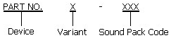
Product
Identification System
Device
TK3x
TK30 series Tank
Controller
Variant
Blank
Standard,
Equal to P Variant in TK60 series
S
Support S.BUS
interface
P
Sound
Programmable
G2
GBS version
Sound Pack
T1
Tiger I
KT
King Tiger
CH2_V1
Challenger 2
ver. 1
.....
Refer to TK Sound Pack webpage for more
information
Accessories
Part Number
Description
Price(USD)
Configuration IR Remote
For
Tank Personalization function
$ 10
IR005
Std. IR battle
emitter kit
$ 2
IR010
High
Power IR battle
emitter kit
$ 5
F003
LED
Main Gun Flasher kit, include
3mm White LED *1, Cable connector *1
$ 2
CAB001
1.25mm pitch cable
connector for connecting IR LED or Gun Flash LED
$ 1
4-CH
Conventional PWMmode control
scheme
TK35:
Engine sound on/off
Cannon elevation
Booming
Cannon ( For TK35 )
Booming
Cannon
(For TK35G1 & TK35G2)
Gun Barrel
Stabilizer on/off (For TK35G2)
Fire
MG: Number of burst is controlled by the time of stay.
Head
light control on/off
AUX Power on/off (Only
available when Main Gun Function Mode is
set to
Gun elevation servo Mode)
Tank move
forward and backward
Right and
Left turn
Turret rotation
TK37/TK37G2/TK39P/TK39PG2:
Booming
Cannon
主砲射擊
None G2
version:
FireMG2 (Servo
Elevation Mode)
G2 version: Gun Barrel
Stabilizer on/off
非G2版:機槍2射擊(啟動機槍2模式下)
G2版: 機槍1射擊
Cannon elevation
主砲俯仰
Turret rotation
砲塔迴轉
Natural Gear Shift In/Out :
Track motor does not move when
shift to natural gear
履帶馬達安全開關
Engine sound on/off
引擎啟動/關閉
Fire MG1:
機槍1射擊
Head
light control on/off
頭燈開/關
Tank move
forward and backward
前進後退
Right and
Left turn
左右轉
10-CH
S.BUS
mode control
scheme
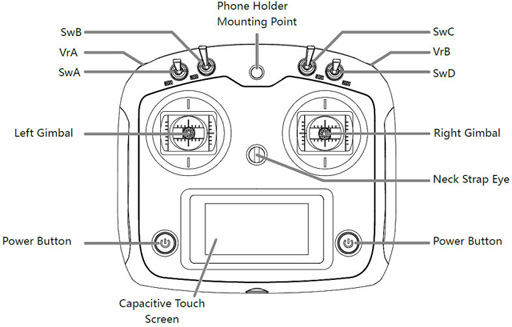
Transmitter: FS-i6S, self-centering VrA
and VrB type Radio
Layout
Command
S.BUS
Channel
assignment
Tank Right
and Left turn
左右轉
CH1 (Stick)
Tank move
forward and backward
前進後退
CH2 (Stick)
Cannon elevation
主砲俯仰
CH3
(Stick)
Turret rotation
砲塔迴轉
CH4
(Stick)
SwB: Up
SwC: Center -> Up
Natural Gear Shift In/Out
主馬達安全開關
Assign SwB to CH7
Assign SwC to CH8
SwB: UP
SwC: Center -> Down
Engine start/stop
引擎啟動/關閉
Assign SwB to CH7
Assign SwC to CH8
SwB: Center
SwC: Center -> Up
NA
無功能
Assign SwB to CH7
Assign SwC to CH8
SwB: Center
SwC: Center -> Down
NA
無功能
Assign SwB to CH7
Assign SwC to CH8
SwB: Down
SwC: Center -> UP
NA
無功能
Assign SwB to CH7
Assign
SwC to CH8
SwB: Down
SwC: Center -> Down
Head
light On/Off
頭燈開/關
Assign SwB to CH7
Assign SwC to CH8
SwA
UP: Smoke
Unit On
DW: Smoke
Unit Off
上:發煙器開啟
下:發煙器關閉
Assign SwA to CH5
SwB
NA
無功能
Assign SwB to CH6
VrA
UP: Booming Cannon
MID:
DW: FireMG1
上:主砲射擊
下:機槍1射擊
Assign VrA to CH9
VrB
UP: Gun Barrel
Stabilizer On/Off (TK37SG2)
MID:
DW: Fire
MG2
上:砲穩系統開啟/關閉
下:機槍2射擊
Assign VrB to CH10
V2.1 and above / V3.x
Layout
Command
S.BUS
Channel
assignment
Tank Right
and Left turn
CH1 (Stick)
Tank move
forward and backward
CH2 (Stick)
Cannon elevation
CH3
(Stick)
Turret rotation
CH4
(Stick)
SwB: Up
SwC: Center -> Up
Natural Gear Shift In/Out
Assign SwB to CH7
Assign SwC to CH8
SwB: UP
SwC: Center -> Down
Engine start/stop
Assign SwB to CH7
Assign SwC to CH8
SwB: Center
SwC: Center -> Up
Aux Light, Ex. convoy
light
Assign SwB to CH7
Assign SwC to CH8
SwB: Center
SwC: Center -> Down
Aux Light 2, Ex. Search light
Assign SwB to CH7
Assign SwC to CH8
SwB: Down
SwC: Center -> UP
Smoke
Unit On/Off
Assign SwB to CH7
Assign
SwC to CH8
SwB: Down
SwC: Center -> Down
Head
light On/Off
Assign SwB to CH7
Assign SwC to CH8
SwA
N/A
Assign SwA to CH5
SwB
N/A
Assign SwB to CH6
SwB: Up
VrA
UP: GBS On/Off ( G2 variant )
MID:
DW: Fire Loader's
MG(MG2)
Assign VrA to CH9
SwB: Up
VrB
UP: Fire Cannon
MID:
DW: Fire Coaxial
MG(MG1)
Assign VrB to CH10
※
V2.1 and above software release
TK35/TK37 Specification
Parameter
Unit
Maximum current of track ESC
7
A
Maximum current of turret and
cannon elevation ESC
7
A
Maximum current of Smoker Driver
7
A
Maximum supply
voltage
7.4
V
Minimum supply
voltage
7.2
V
TK39 Specification
Parameter
Unit
Maximum current of track ESC
7
A
Maximum current of turret and
cannon elevation ESC
7
A
Maximum current of Smoker Driver
7
A
Maximum supply
voltage
11.1
V
Minimum supply
voltage
7.2
V
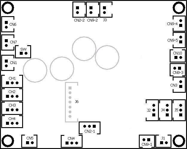
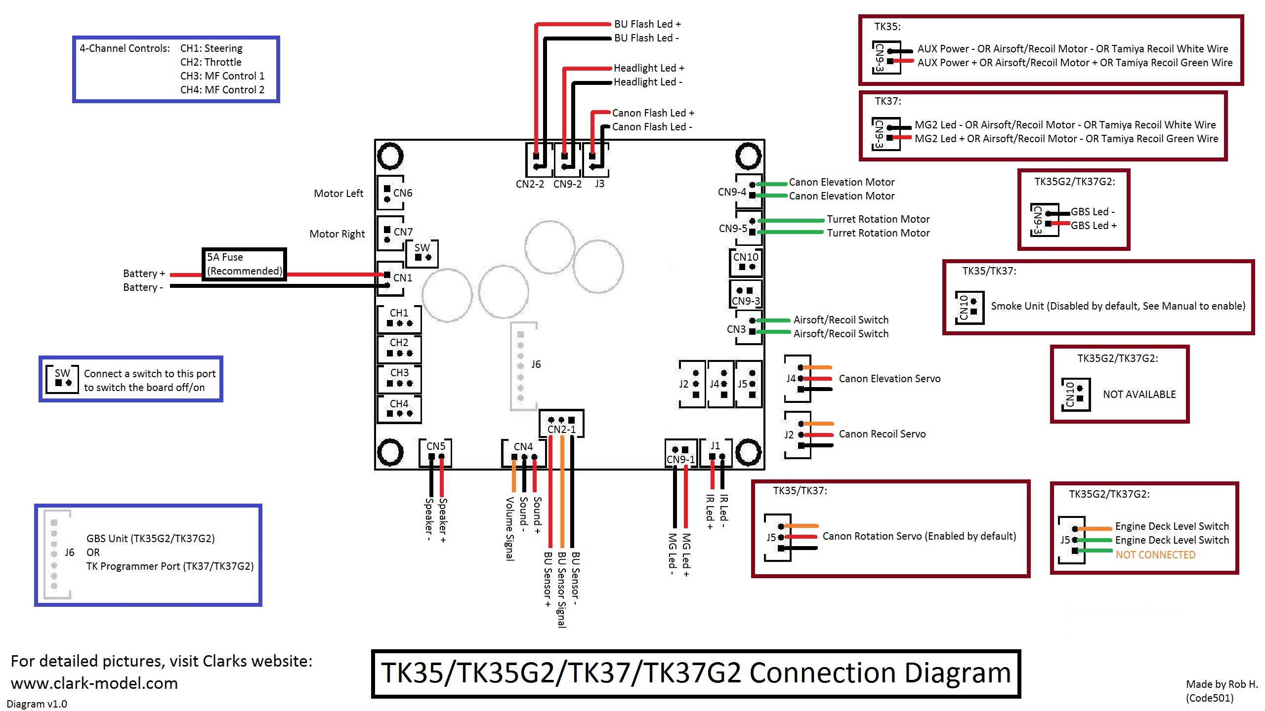
TK35/TK37 Connector layout
Connection diagram( Click to download full size image )
TK35 Connector and pin assignments
Connector
Description
Main Gun Function Mode is
set to
Gun elevation servo Mode
-H version, or Main Gun
Function Mode is configured to AirSoft
or HL Recoil
-T version, or Main Gun Function Mode is configured to
TAMIYA
Recoil
SW
Switch Cable Port
Connect to a switch
CN1
Battery Power
1. Battery +
2.
Battery -
CN2-1
Infrared RX Port
1.
HBU/TBU -
2.
HBU/TBU SIG
3.
HBU/TBU +
CN2-2
Infrared LED Port
1. TBU FLASH LED +
2. TBU FLASH LED -
CN3
Sync Switch Port
1. Not Used
2. Not Used
*Default setting
1. AirSoft/Recoil Switch
2. AirSoft/Recoil Switch
1. TAMIYA Recoil Unit Switch
2. TAMIYA Recoil Unit Switch
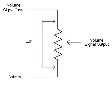
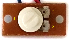
CN4
Sound
Volume
1.
Volume Signal
Output (
Wiper pin of VR
)
2. Battery -( 1 outside pin of
VR )
3.Volume
Signal
Input (
1 outside pin of VR )
CN5
Speaker
1.
Speaker -
2.
Speaker +
CN6
Motor Left
CN7
Motor
Right
CH1
Steering control signal,
Futaba: CH1
JR:AILE
CH2
Throttlecontrol signal
Futaba:
CH2( Mode 2) or CH3 ( Mode 1 )
JR:ELEV
CH3
Multi function control signal 1
Futaba:
CH3( Mode 2) or CH2(
Mode 1 )
JR:THRO
CH4
Multi function control signal 2
Futaba: CH4
JR:RUOD
CN9-1
Upper
Hull Functions2
1. Machine gun LED+
2.
Machine gun LED-
CN9-2
Upper
Hull Functions2
1.
Head Light LED+
2.Head
Light LED-
CN9-3
Upper
Hull Functions3
1. AUX
Power+
2. AUX Power-
1.AIRSOFT/RECOIL
Motor+
2. AIRSOFT/RECOIL Motor-
1. TAMIYA
Recoil unit
green Wire
2. TAMIYA Recoil unit white Wire
CN9-4
Upper
Hull Functions4
1. GUN ELEVATE MOTOR+
2. GUN ELEVATE MOTOR-
CN9-5
Upper
Hull Functions5
7. TURRET MOTOR+
8. TURRET MOTOR-
CN10
Smoke
Unit
Disabled by default, See
Turret/Gun Rotate Servo
Enable function to enable.
J1
IR Battle Emitter Port
To work
with IR battle emitter(IR010)
1. IR LED +
2. IR LED -
J2
RealRecoil Servo Port
1. Battery - (Black Wire)
2.
+5V ( Red Wire)
3. Signal( White Wire)
See
RealRecoil section in Assembly Guide
J3
LED Main Gun Flasher
Port
To Work
with LED
Main Gun Flasher(F003)
1. LED +
2. LED -
J4
Gun Elevation Servo
Port
1. Battery - (Black
Wire)
2.
+5V ( Red Wire )
3. Signal( White Wire)
Not Used
J5
Turret/Gun Rotate Servo
Port
1. Battery - (Black
Wire)
2.
+5V ( Red Wire )
3. Signal( White Wire)
*CN10
is no longer functional when this port is enabled
TK35G2 Connector and pin assignments
Connector
Description
Pin assignments
SW
Switch Cable Port
Connect to a switch
CN1
Battery Power
1. Battery +
2.
Battery -
CN2-1
Infrared RX Port
1.
HBU/TBU -
2.
HBU/TBU SIG
3.
HBU/TBU +
CN2-2
Infrared LED Port
1. TBU FLASH LED +
2. TBU FLASH LED -
CN3
Sync Switch Port
1. Not Used
2. Not Used
*Default setting
CN4
Sound
Volume
1.
Volume Signal
Output (
Wiper pin of VR
)
2. Battery -( 1 outside pin of
VR )
3.Volume
Signal
Input (
1 outside pin of VR )
CN5
Speaker
1.
Speaker -
2.
Speaker +
CN6
Motor Left
CN7
Motor
Right
CH1
Steering control signal,
Futaba: CH1
JR:AILE
CH2
Throttlecontrol signal
Futaba:
CH2( Mode 2) or CH3 ( Mode 1 )
JR:ELEV
CH3
Multi function control signal 1
Futaba:
CH3( Mode 2) or CH2(
Mode 1 )
JR:THRO
CH4
Multi function control signal 2
Futaba: CH4
JR:RUOD
CN9-1
Upper
Hull Functions2
1. Machine gun LED+
2.
Machine gun LED-
CN9-2
Upper
Hull Functions2
1.
Head Light LED+
2.Head
Light LED-
CN9-3
Upper
Hull Functions3
1. GBS LED+
2. GBS LED-
CN9-4
Upper
Hull Functions4
1. GUN ELEVATE MOTOR+
2. GUN ELEVATE MOTOR-
CN9-5
Upper
Hull Functions5
7. TURRET MOTOR+
8. TURRET MOTOR-
CN10
Smoke
Unit
Not Available
J1
IR Battle Emitter Port
To work
with IR battle emitter(IR010)
1. IR LED +
2. IR LED -
J2
RealRecoil Servo Port
1. Battery - (Black Wire)
2.
+5V ( Red Wire)
3. Signal( White Wire)
See
RealRecoil section in Assembly Guide
J3
LED Main Gun Flasher
Port
To Work
with LED
Main Gun Flasher(F003)
1. LED +
2. LED -
J4
Gun Elevation Servo
Port
1. Battery - (Black Wire)
2.
+5V ( Red Wire )
3. Signal( White Wire)
J5
Engine Deck Level Switch Port
1.
Not connected
2.
SWITCH
3.
SWITCH
* To
close Pin1 and Pin2 when gun barrel travels above engine deck
J6
GBS
Unit
Port
To
connect GBS (Gun Barrel Stabilizer) unit
TK37 Connector and pin assignments
Connector
Description
Main Gun Function Mode is
set to
Gun elevation servo Mode
-H version, or Main Gun
Function Mode is configured to AirSoft
or HL Recoil
-T version, or Main Gun Function Mode is configured to
TAMIYA
Recoil
SW
Switch Cable Port
Connect to a switch
CN1
Battery Power
1. Battery +
2.
Battery -
CN2-1
Infrared RX Port
1.
HBU/TBU -
2.
HBU/TBU SIG
3.
HBU/TBU +
CN2-2
Infrared LED Port
1. TBU FLASH LED +
2. TBU FLASH LED -
CN3
Sync Switch Port
1. Not Used
2. Not Used
*Default setting
1. AirSoft/Recoil Switch
2. AirSoft/Recoil Switch
1. TAMIYA Recoil Unit Switch
2. TAMIYA Recoil Unit Switch
CN4
Sound
Volume
1.
Volume Signal
Output (
Wiper pin of VR
)
2. Battery -( 1 outside pin of
VR )
3.Volume
Signal
Input (
1 outside pin of VR )
CN5
Speaker
1.
Speaker -
2.
Speaker +
CN6
Motor Left
CN7
Motor
Right
CH1
Steering control signal,
Futaba: CH1
JR:AILE
CH2
Throttlecontrol signal
Futaba:
CH2( Mode 2) or CH3 ( Mode 1 )
JR:ELEV
CH3
Multi function control signal 1
Futaba:
CH3( Mode 2) or CH2(
Mode 1 )
JR:THRO
CH4
Multi function control signal 2
Futaba: CH4
JR:RUOD
CN9-1
Upper
Hull Functions2
1.
MG LED+
2.
MG LED-
CN9-2
Upper
Hull Functions2
1.
Head Light LED+
2. Head
Light LED-
CN9-3
Upper
Hull Functions3
1.
MG2 LED+
2.
MG2 LED-
1.AIRSOFT/RECOIL
Motor+
2. AIRSOFT/RECOIL Motor-
1. TAMIYA
Recoil unit
green Wire
2. TAMIYA Recoil unit white Wire
CN9-4
Upper
Hull Functions4
1. GUN ELEVATE MOTOR+
2. GUN ELEVATE MOTOR-
CN9-5
Upper
Hull Functions5
7. TURRET MOTOR+
8. TURRET MOTOR-
CN10
Smoke
Unit
Disabled by default, See
Turret/Gun Rotate Servo
Enable function to enable.
J1
IR Battle Emitter Port
To work
with IR battle emitter(IR010)
1. IR LED +
2. IR LED -
J2
RealRecoil Servo Port
1. Battery - (Black Wire)
2.
+5V ( Red Wire)
3. Signal( White Wire)
See
RealRecoil section in Assembly Guide
J3
LED Main Gun Flasher
Port
To Work
with LED
Main Gun Flasher(F003)
1. LED +
2. LED -
J4
Gun Elevation Servo
Port
1. Battery - (Black
Wire)
2.
+5V ( Red Wire )
3. Signal( White Wire)
Not Used
J5
Turret/Gun Rotate Servo
Port
1. Battery - (Black
Wire)
2.
+5V ( Red Wire )
3. Signal( White Wire)
*CN10
is no longer functional when this port is enabled
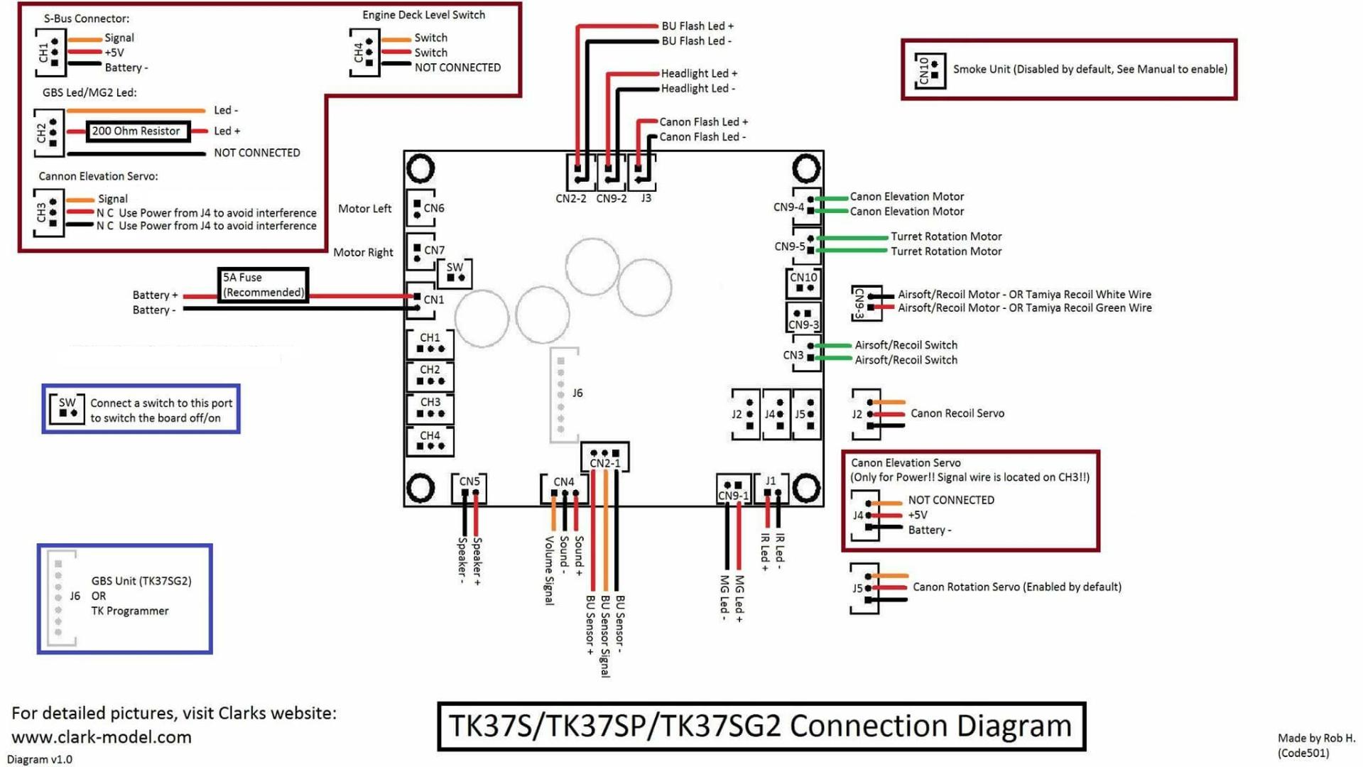
TK37S/TK37SP/TK37SG2 Connector and pin assignments
Connector
Description
Main Gun
Function Mode is configured to AirSoft
or HL Recoil
Main Gun Function Mode is configured to
TAMIYA
Recoil
SW
Switch Cable Port
Connect to a switch
CN1
Battery Power
1. Battery +
2.
Battery -
CN2-1
IR Battle
Receiver Port
1.
HBU/TBU -
2.
HBU/TBU SIG
3.
HBU/TBU +
CN2-2
IR Battle IndicatorPort
1. TBU FLASH LED +
2. TBU FLASH LED -
CN3
Sync Switch Port
1. AirSoft/Recoil Switch
2. AirSoft/Recoil Switch
1. TAMIYA Recoil Unit Switch
2. TAMIYA Recoil Unit Switch
CN4
Sound
Volume
1.
Volume Signal
Output (
Wiper pin of VR
)
2. Battery -( 1 outside pin of
VR )
3.Volume
Signal
Input (
1 outside pin of VR )
CN5
Speaker
1.
Speaker -
2.
Speaker +
CN6
Motor Left
CN7
Motor
Right
CH1
S.BUS
1. Battery -
2. +5V
3. Signal
CH2
GBS/MG2 LED
Connect to a GBS/MG2 LED:
1. Not Connected
2. --->200ohm in-serial resistor --> LED +
3.
LED -
CH3
Gun Elevation Servo Signal
Port
1. Not connected, use power from J4 to avoid interference.
2. Not connected, use power from J4 to avoid interference.
3. Signal, connect to servo white/yellow wire
CH4
Engine Deck Level Switch Port
1.
SWITCH
2.
SWITCH
3.
Not Connected
* To
close Pin1 and Pin2 when gun barrel travels above engine deck
CN9-1
Upper
Hull Functions1
1.
MG LED+
2.
MG LED-
CN9-2
Upper
Hull Functions2
1.
Head Light LED+
2. Head
Light LED-
CN9-3
Upper
Hull Functions3
1.AIRSOFT/RECOIL Motor+
2.AIRSOFT/RECOIL Motor-
1. TAMIYA
Recoil unit
green Wire
2. TAMIYA Recoil unit white Wire
CN9-4
Upper
Hull Functions4
1. GUN ELEVATE MOTOR+
2. GUN ELEVATE MOTOR-
CN9-5
Upper
Hull Functions5
7. TURRET MOTOR+
8. TURRET MOTOR-
CN10
NA
1. Smoke
unit +
2. Smoke
unit -
J1
IR Battle Emitter Port
To work
with IR battle emitter(IR010)
1. IR LED +
2. IR LED -
J2
RealRecoil Servo Port
1. Battery - (Black Wire)
2.
+5V ( Red Wire)
3. Signal( White Wire)
See
RealRecoil section in Assembly Guide
J3
LED Main Gun Flasher
Port
To Work
with LED
Main Gun Flasher(F003)
1. LED +
2. LED -
J4
Gun Elevation Servo Power Port
1. Battery -, connect to servo black/brown Wire
2.
+5V, connect to servo red wire
3.
Not Connected
J5
Turret/Gun
Rotate Servo
Port
1. Battery - (Black
Wire)
2.
+5V ( Red Wire )
3. Signal( White Wire)
J6
Programming and GBS unit Port
To connect TK Programmer or
GBS unit
Connection diagram( Click to
download full size image )
TK39
Connector layout
CN2-1 and CN9-1 direction are
changed.
TK39P/TK39PG2
Connector
Description
Pin assignment
Upper
Hull Functions (CN9) Mode
Airsoft
Tamiya Recoil
TK39/TK39P: MG2
Mode
TK39PG2: GBS Mode
SW
Switch Cable
Port
Connect to a switch
CN1
Battery
Power
1. Battery +
2.
Battery -
CN2-1
Infrared Port
1.
HBU/TBU -
2.
HBU/TBU SIG
3.
HBU/TBU +
CN2-2
Infrared Port
1. TBU FLASH LED +
2. TBU FLASH LED -
CN3
Sync Switch Port
1. AirSoft Switch
2. AirSoft Switch
1. TAMIYA Recoil Unit Switch
2. TAMIYA Recoil Unit Switch
TK39/TK39P:
1.
Not Connected
2.
Not Connected
TK39PG2:
1.
Engine Deck Switch
2.
Engine Deck Switch
CN4
Sound Volume
1. Volume Signal
Output (
Wiper pin of VR
)
2. Battery -( 1 outside
pin of VR )
3.Volume
Signal
Input (
1 outside pin of VR )
CN5
Speaker
1.
Speaker -
2. Speaker +
CN6
(*x/1)
Ultrasonic
ESC1
Connect to left track/steering motor
CN7
(*2/2)
Ultrasonic
ESC2
Connect to right track/propulsion
motor
CH1
Steering control signal
1. Battery -
2. +5V
3. Signal
CH2
Throttlecontrol signal
1. Battery -
2. +5V
3. Signal
CH3
(*2/0)
Multi function control signal 1
1. Battery -
2. +5V
3. Signal
CH4
Multi function control signal 2
1. Battery -
2. +5V
3. Signal
CN9-1
Upper
Hull Functions1
1.
MG LED+
2.
MG LED-
CN9-2
Upper
Hull Functions2
1.
Head Light LED+
2. Head
Light LED-
CN9-3
Upper
Hull Functions3
1.AIRSOFT Motor+
2.AIRSOFT Motor-
1. TAMIYA
Recoil unit
green Wire
2. TAMIYA Recoil unit white Wire
TK39P:
1.
-> 200ohm->
MG2 LED+
2.
MG2 LED-
TK39PG2:
1.
Not connected
2.
Not connected
CN9-4
Upper
Hull Functions4
1. GUN ELEVATE MOTOR+
2. GUN ELEVATE MOTOR-
CN9-5
Upper
Hull Functions5
7. TURRET MOTOR+
8. TURRET MOTOR-
CN10
(*3/0)
Smoke Unit
Connect to smoke unit
J1
IR Battle Emitter
Port
To work with IR battle
emitter(IR010)
1. IR LED +
2. IR LED -
J2
(*5)
RealRecoil Servo Port
RealRecoil Servo Port is always
turned ON, no setting is needed to turn it on
1. Signal( White Wire)
2. +5V ( Red Wire)
3. Battery - (Black Wire)
J3
Cannon Flash Port
1.
Cannon Flash
LED +
2.
Cannon Flash
LED -
J4
(*1/5)
Gun Elevation Servo Port
1. Battery -
2. +5V
3. Signal
J5
(*3/3)
Turret/Gun
traverse Servo
Port
1. Battery -
2. +5V
3. Signal
J6
Programming and GBS unit Port
To connect TK Programmer or
GBS unit
TK39SP/TK39SPG2
Connector
Description
Upper
Hull Functions (CN9) Mode
Airsoft
Tamiya Recoil
SW
Switch Cable
Port
Connect to a switch
CN1
Battery
Power
1. Battery +
2.
Battery -
CN2
Infrared Port
1. HBU/TBU +
2. HBU/TBU SIG
3.
HBU/TBU -
4. TBU FLASH LED -
5. TBU FLASH LED +
CN3
Gun Flash
Port
1. Battery +
2. Strobe Trigger
3.
Battery -
4. AirSoft/Recoil Switch
5. AirSoft/Recoil Switch
1. Battery +
2. Strobe Trigger
3.
Battery -
4. TAMIYA Recoil Unit Switch
5. TAMIYA Recoil Unit Switch
CN4
Sound Volume
1. Volume Signal
Output (
Wiper pin of VR
)
2. Battery -( 1 outside
pin of VR )
3.Volume
Signal
Input (
1 outside pin of VR )
CN5
Speaker
1.
Speaker -
2. Speaker +
CN6
(*x/1)
ESC1
Connect to left track/steering motor
CN7
(*2/2)
ESC2
Connect to right track/propulsion
motor
CH1
S.BUS
RX
1. Battery -
2. +5V
3. Signal
CH2
N/A
1. Not Connected
2. Not Connected
3.
Not Connected
CH3
(*2/0)
MG2 LED
Connect to a MG2 LED:
1. N/C
2. LED +
3.
LED -
CH4
Engine Deck Level Switch Port
1.
NO CONNECTION.
2.
SWITCH
3.
SWITCH
* To
close Pin1 and Pin2 when gun barrel travels above engine deck
CH3※1
Engine Deck Level Switch Port
1.
NO CONNECTION.
2.
SWITCH
3.
SWITCH
* To
close Pin1 and Pin2 when gun barrel travels above engine deck
CH4※1
MG2 LED
Connect to a MG2 LED:
1. N/C
2. LED +
3.
LED -
CN9-1
Upper
Hull Functions1
1.
MG LED+
2.
MG LED-
CN9-2
Upper
Hull Functions2
1.
Head Light LED+
2. Head
Light LED-
CN9-3
Upper
Hull Functions3
1.AIRSOFT Motor+
2.AIRSOFT Motor-
1. TAMIYA
Recoil unit
green Wire
2. TAMIYA Recoil unit white Wire
CN9-4
Upper
Hull Functions4
1. GUN ELEVATE MOTOR+
2. GUN ELEVATE MOTOR-
CN9-5
Upper
Hull Functions5
7. TURRET MOTOR+
8. TURRET MOTOR-
CN10
(*3/0)
Smoke Unit
Connect to smoke unit
J1
IR Battle Emitter
Port
To work with IR battle
emitter(IR010)
1. IR LED +
2. IR LED -
J2
(*5)
RealRecoil Servo Port
RealRecoil Servo Port is always
turned ON, no setting is needed to turn it on
1. Signal( White Wire)
2. +5V ( Red Wire)
3. Battery - (Black Wire)
J3
Cannon Flash Port
1.
Cannon Flash
LED +
2.
Cannon Flash
LED -
J4
(*1/5)
Gun Elevation Servo Port
1. Battery -
2. +5V
3. Signal
J5
(*3/3)
Turret/Gun
traverse Servo
Port
1. Battery -
2. +5V
3. Signal
J6
Programming and GBS unit Port
To connect TK Programmer or
GBS unit
※1
V2.3 and above
Assembly Guide
Set Main Gun
Function Mode to match your tank
hardware configuration (HL AirSoft, HL Recoil or TAMIYA Recoil),
Disconnect RX-18 and plug cables to the same connector on TK board,
Set
Sound Volume to middle
Connect a switch
cable (for example, HL Smoke Unit Switch Cable)
to
Switch Cable Port as power switch. Because HL tank already have
power switch on battery cable, you can just to short
Switch Cable Port's two pins or connect to a switch cable and keep it
switched on.
Connect
channel cables to receiver according to RC
mode( See picture "TK series connector and pin assignments" ) . if you are not sure what mode you RC system is, just swap CH2 and CH3 and
try again. TK20 board has BEC( Battery
eliminate
circuit),
can power receiver through channel cables, no additional battery is needed for
receiver
Set CH1,
2 and 3 trimmer on transmitter to center position, Set CH4 trimmer on
transmitter to most left or right position,
Connect power adaptor( See FAQ )
Switch on TK board and transmitter, you should hear
turret traverse
sound. if not, please contact us.
gently
move CH4(Multi
function control signal 2)
trimmer to center till
turret traverse is gone.
gently
move CH2(Throttle )
trimmer up and down if you hear motor hum sound.
Cannon
firing sound should be generated and
recoil servo should moves when move
CH3 stick to most top position, if not, gently move CH3(Multi
function control signal 2 )
trimmer up and down till
it work correctly.
You are
all set
Disconnect power adaptor and connect battery( make sure that battery is fully
charged).
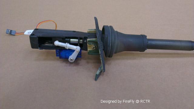
RealRecoil(
Patent Pending)
servo port allows you to recreate real gun barrel recoil movement with single &
cheap servo, what you need to do is to link servo and gun barrel then RealRecoil takes
the rest. direction of servo movement can be set by user, please see section "Tank
Personalization"
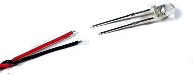
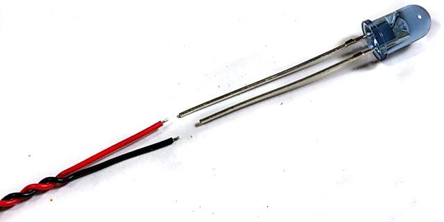
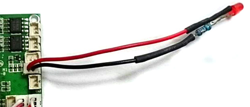
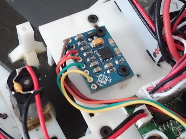
LED GUN FLASHER Installation:
A white LED and cable connector are needed( Part Number
is F003)
Solder color wire (red wire in
this example) to long pin of white LED, black wire(-) to short pin,
Plug cable into J3.
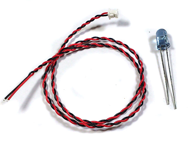
IR battle emitter Installation
An IR LED and cable connector are needed( Part
number is IR005/IR010 ).
Solder color wire (red wire in
this example) to long pin of IR LED, black wire(-) to short pin,
Plug cable into J1.
Gun Barrel Stabilizer(GBS)
overview and installation
GSU is an
optional module of TK35. When GSU is turned on, it
detects the tank movement and
compensate gunrotation and elevation
to stabilize the gun automatically.
When GBS is turned on, operator can still change gun elevation and direction
under GBS compensation, GSU have the following features:
-
2-axis gun stabilization in turret rotation and gun
elevation.
-
Fully programmable gun elevation
real angle calculator allows GBS to work with different elevation
setup
,
- Fully programmable turret motor
controller allows GBS to work with different motor/gear box
setup,
- Auto reload position, Gun barrel goes to to
reload position after fire, and return to last position when reload when reload
time expired,
-
Adjustable
Engine deck level,
-
Adjustable auto reload position,
- GBS
unit d
imensions: 20 x
16 x 3mm.
- Unified platform design,
allows all existing TK35 can be shipped back to us to upgrade to TK35G2
Servo for GBS -
-Control
System: +Pulse Width Control 1520usec Neutral
-Required Pulse: 3-5 Volt Peak to Peak Square Wave
-Operating Voltage: 4.8-6.0 Volts
-Operating Angle: 45 Deg. one side
Power on GBS
calibration -
When power
on TK35G2, GSU starts a reset
process and must be kept stationary.
Head Light LED(
Or GBS Indicator before software version 3) is turned ON during
GBS calibration and you must
not to move the tank during
calibration. GBS unit is very sensitive and you should nottouch or vibrate the GBS
unit during power on reset. The process will take
around 2 seconds. Head Light LED will
be turned off when
calibrationcompleted.
If error occurred duration calibration, such as no GBS
unit connected, wrong wring, Head Light LED will not goes off.
An in-series 200-ohm resistor is needed for GBS LED
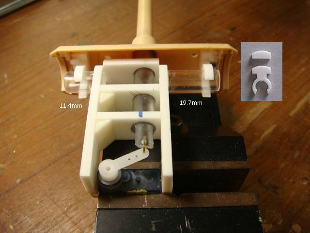
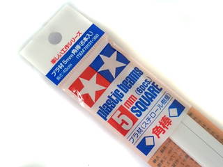
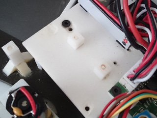
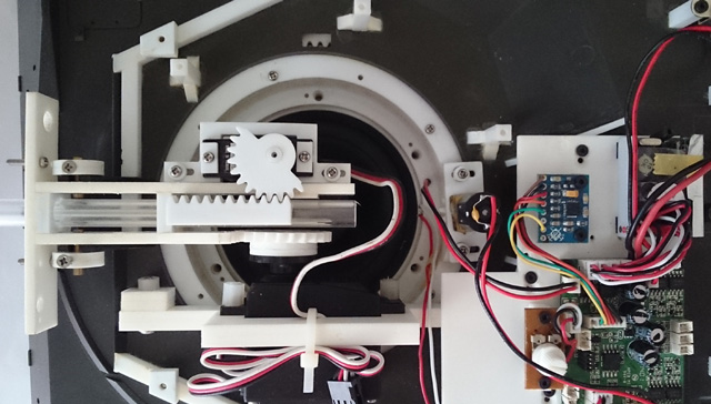
Mounting of GBS
-
The GBSunit must be mounted securely and
horizontally on the turret, here is an example, first
to use Tamiya 5mm square beam, cut into 5~6mm in length, make 1.6mm hole, then
glue to turret floor by cement
Bolt GBS unit with the screws came with GBS unit, and plug
connector to J6 port on TK22G2
For
accurate motion detection, it must be kept
within 5 degree with turret base plate.
mounting directions is as
shown in following picture. Servo
for elevation is Futaba S3003 in this
setup.
Turning GBS
on/off -
GBS can be turned on/off by move
right stick to top, move left stick to right, you can also hear click sound when
turn it on and off
Adjusting gun elevation angle -
The gun elevation
V gain setting is used to adjust the
amount of
gun elevation servo angle
to meet different mechanical setup. adjusting
procedures
are
-First to put TK35G2 board in IR programming mode.
-Turn
GBS on and moves the gun
barrel
to horizontal position.
-Tilt the tank for 15-20
degree.
-Use IR configure remote to
adjustservo gain value until the gun is
horizontal again.
-Power off TK35G2 board, remove
jumper and turn power again to leave
IR programming mode.
Adjusting gun elevation angle
calculator gains -
The angle
calculator's fast gain and slow gain settingsare used to adjust the
angle calculation, adjusting procedures are
-First to put TK22G board in IR programming mode.
-Turn GSU on and moves the gun
barrel
to horizontal position.
-Tilt the tank for 10-20
degree.
-Rotate turret in various speed
( from low to full speed), if elevation speed is too slow, increase slow gain a
bit, otherwise, reduce slow gain,
-rotate turret to 12 o'clock position,
tilt the tank
hull about 15-20
degree in various speed,if
elevation speed is too slow, can not keep up tank hull
tilt speed, increase fast gain a bit, if elevation moves faster the hull tile
speed and over the position it should be (overshoot), decrease fast gain a bit
-Power off TK22G board, remove
jumper and turn power again to leave
IR programming mode.
Adjusting
turret rotation motor control gains -
The turret rotation motor P , I and
D gainare used to
meet the characteristic of turret rotate motor and design on your tank. adjusting procedures are as the following.
-First to put TK22G board in IR programming mode.
-Turn GSU on
-Rotate
tank hull from stationary
to low speed, if turret motor does start well when tank rotation start, increase
start gain a bit, if turret motor runs too fast (overshoot) , decrease start
gain a bit.
-Rotate
tank hull in various speed( low,
middle and full) , if turret rotation speed is too slow, can't keep up hull
rotation, increase speed gain, otherwise, reduce speed gain,
-Stop
tank hull rotation from various
speed, if turret stops too early, decrease stop gain, if turret stops too late
increase stop gain.
Tank
Personalization( Patent Pending)
Settings
of TK series board can be set by
Configuration IR REMOTE. TAMIYA battle unit(TBU),
Heng-Leog battle
unit(HBU), or our programming line is required as IR command receiver. red "*"
sign means default setting
Type of Tank
determines
Battle Date when doing IR battle( See
Variants section
)
Type of
Tank
TankMobility,
Turret rotation and Gun barrel evaluation speed
Note:
Suggested Value, can be changed by Reload Time and
Invulnerability time setting function
Steps
to set parameters:
STEP 1:
TURN POWER OFF.
STEP 2: Install TBU/HBU,
STEP 3: Install a jumper on J2
pin 2 and pin 3,
STEP 4:TURN
POWER ON.
STEP 5: Point
Configuration IR remote to
TBU/HBU,
refer to function table listed below and press the
button
of function that you want to set,
STEP 6: Indicator on
TBU/HBU flashes according to
the setting value.
STEP 7:TURN POWER OFF,
STEP 8:
remove jumper on J2, then power
on and you are set.
Function tables:
Function Page Selection:
Press "-/--" Key on TV remote to select.
Available Settings
Indicator
flashes times
Description
Select
settings on Page 1
1*
TK board
goes back to this page after power on
Select settings on Page 2
2
Select settings on Page 3
3
Select settings on Page 4
4
*Text in black means that
setting function is on page1.
Save
current setting to
PRESET 1: Press number
key "1" on TV remote to save,
Available Settings
Indicator
flashes times
Description
Save to PRESET 1
1
Indicator flashes when setting
is saved
Save
current setting to PRESET 2: Press number
key "2" on TV remote to save,
Available Settings
Indicator
flashes times
Description
Save to PRESET 2
2
Indicator flashes when setting
is saved
*Once
you've adjusted everything, you can
push "1" or
"2" to save
current setting to PRESET 1
or 2. If you don't do this saving the board remembers
the last settings.
Use saved settings:
Press "ENT" or "SOUND MODE" Key on TV remote to select.
Available Settings
Indicator
flashes times
Description
Use PRESET 1
setting
1
UsePRESET 2 setting
2
Use Factory Default Setting
( Read-Only )
3
To
restore factory
default value in case of setting data is messed up.
*To
switch between the presets you press either "sound
mode" or "enter" button, once the preset is selected,
switch tank off and remove setup jumper. Switch back on and away you
go.
Mixer Mode:
Press
(MUTE) key on TV remote to select.
Available Settings
Indicator flashes times
Description
Mixer Mode
1
1*
Tank mode 1
CH1 controls
rudder, CH2
controls throttle.
Proportional steering,
sharp and pivot turn* are supported
Left Track
Right Track
Pivot
Turn
Sharp
Turn
Proportional
Steering
Proportional
Steering
Sharp
Turn
Pivot
Turn
Mixer Mode
2
2
OFF mode
CH1
controls left track, CH2 controls right track
Mixer Mode
3
3
Tank mode 2
CH1 controls
rudder, CH2
controls throttle,
Proportional steering and
sharp turn are supported
Left Track
Right Track
Sharp
Turn
Proportional
Steering
Proportional
Steering
Sharp
Turn
Mixer Mode4
4
Half-Track mode
CH1 controls
rudder, CH2
controls throttle,
Support proportional steering only.
Max. turn
ratio ( speed ratio of left and right track at hard left and right turn)
can be
configured form large (4)
to small (8)
※Available Setting is ALWAYS from TAMIYA Recoil MODE when power is
applied, then go to HL Airsoft Mode( indicator flashes 2 times) when POWER key is pressed first time,
It does not means that the selected setting before power off is not saved.
No mobility damage simulation, Speed is not
reduced when Tank is in badly damaged state.
-12.5%
2
-25%
3*
-37.5%
4
-50%
5
-62.5%
6
-75%
7
-87.5%
8
Armor type:
press number
key "9" on TV remote to select
Available Settings
Indicator
flashes times
Description
Heavy Armor
1*
Resistance to machine gun
Soft
skin, like Trucks
2
No resistance to machine gun
Sending IR code when firing
machine gun:
press number
key "6" on TV remote to select
Available Settings
Indicator
flashes times
Description
Not
to send
MG
IR code
1*
To send MG IR code
2
Primary weapon reload time:
press number
key "4" on TV remote to select
Available Settings
Indicator
flashes times
Description
3 seconds
3
4 seconds
4
5 seconds
5
6 seconds
6
7 seconds
7
8 seconds
8
9 seconds
9*
10
seconds
10
11 seconds
11
12
seconds
12
13
seconds
13
14
seconds
14
15
seconds
15
Rounds of Primary weapon:
press number
key "8" on TV remote to select,
Available Settings
Indicator
flashes times
Description
Not
limited
1*
8 rounds
2
16 rounds
3
24 rounds
4
32 rounds
5
40 rounds
6
48 rounds
7
56 rounds
8
64 rounds
9
72 rounds
10
80 rounds
11
88 rounds
12
96 rounds
13
104 rounds
14
112
rounds
15
120
rounds
16
Primary weapon
IR code:
press number key "0" on TV
remote to select
Available Settings
Indicator
flashes times
Description
TAMIYA 1/16 cannon code
1*
For TAMIYA 1/16 IR battle
HL cannon code
2
For HL IR battle
Repair code
3
For Bergepanzer
application,
damage count decreased by 1 when this IR
code is received, each repair needs 15s, no other vehicle
can damage vehicle that is under this mode
Machine Gun code
4
Vehicle
with MG
TAMIYA 1/35 cannon code
5
For TAMIYA 1/35 IR battle
VSTANK cannon code
6
For VSTANK IR battle
Reserved
7
Reserved
Reserved
8
Reserved
Invulnerability time:
Vehicle is Invulnerable during
this period,
press number
key "7" on TV remote to select
Available Settings
Indicator
flashes times
Description
Vehicle can not be recovered from destroyed mode
1
1 second
2
2 seconds
3
3 seconds
4
4 seconds
5
5 seconds
6
6 seconds
7
7 seconds
8
8 seconds
9
9 seconds
10
10
seconds
11*
TAMIYA
Heavy tank
11
seconds
12
12
seconds
13
TAMIYA
Medium tank
13
seconds
14
14
seconds
15
TAMIYA
Light tank
15
seconds
16
Max hit can take:
Press number key "5"
on TV remote to select
Available Settings
Indicator
flashes times
Description
1 round
1
2 rounds
2
3 rounds
3
TAMIYA
Light tank
4 rounds
4
5 rounds
5
6 rounds
6
TAMIYA
Medium tank
7 rounds
7
8 rounds
8
9 rounds
9*
TAMIYA
Heavy tank
10
rounds
10
11
rounds
11
12
rounds
12
13
rounds
13
14
rounds
14
15
rounds
15
*The
following setting function is only available on TK35G2
Function Page Selection:
Press "-/--" Key on TV remote to select. for
TK35G2 only
Available Settings
Indicator
flashes times
Description
Select
settings on Page 1
1*
TK board
goes back to this page after power on
Select settings on Page 2
2
Select settings on Page 3
3
Select settings on Page 4
4
*Text in black means that
setting function is on page1.
GBS LED enable:
press
"TV/VIDEO" or "->[]" Key on TV
remote to select
Available Settings
Indicator
flashes times
Description
Enabled
1*
Disabled
2
*Removed
from Software Version 3.
Horizontal GBS motor Speed gain increase:
Select page 4 , press number
key "1" on TV remote to increase gain
Available Settings
Indicator
flashes times
Description
0
1
:
:
8
9
Horizontal GBS motor Speed gain
decrease:
Select page 4 , press number
key "4" on TV remote to increase gain
Available Settings
Indicator
flashes times
Description
0
1
:
:
8
9
Horizontal GBS motor Start gain
increase:
Select page 4 , press number
key "2" on TV remote to increase gain
Available Settings
Indicator
flashes times
Description
0
1
:
:
8
9
Horizontal GBS motor Start gain
decrease:
Select page 4 , press number
key "5" on TV remote to increase gain
Available Settings
Indicator
flashes times
Description
0
1
:
:
8
9
Horizontal GBS motor Stop gain increase:
Select page 4 , press number
key "3" on TV remote to increase gain
Available Settings
Indicator
flashes times
Description
0
1
:
:
8
9
Horizontal GBS motor Stop gain
decrease:
Select page 4 , press number
key "6" on TV remote to increase gain
Available Settings
Indicator
flashes times
Description
0
1
:
:
16
17
Horizontal GBS
sensitive
increase:
Select page 4 , press number
key "8" on TV remote to increase gain
Available Settings
Indicator
flashes times
Description
0
1
:
:
8
9
Horizontal GBS
sensitive
decrease:
Select page 4 , press number
key "0" on TV remote to increase gain
Available Settings
Indicator
flashes times
Description
0
1
:
:
16
17
Vertical GBS
slow
gainincrease:
Select page 3 , press number
key "1" on TV remote to increase gain
Available Settings
Indicator
flashes times
Description
0
1
:
:
8
9
Vertical GBS
slow
gain
decrease:
Select page 3 , press number
key "4" on TV remote to increase gain
Available Settings
Indicator
flashes times
Description
0
1
:
:
8
9
Vertical GBS
fast
gainincrease:
Select page 3 , press number
key "2" on TV remote to increase gain
Available Settings
Indicator
flashes times
Description
0
1
:
:
8
9
Vertical GBS
fast
gain
decrease:
Select page 3 , press number
key "5" on TV remote to increase gain
Available Settings
Indicator
flashes times
Description
0
1
:
:
8
9
Vertical GBS
servo angle
gainincrease:
Select page 3 , press number
key "8" on TV remote to increase gain
Available Settings
Indicator
flashes times
Description
0
1
:
:
8
9
Vertical GBS
servo angle
gain
decrease:
Select page 3 , press number
key "0" on TV remote to increase gain
Available Settings
Indicator
flashes times
Description
0
1
:
:
8
9
Engine deck level increase:
Select page 3 , press
"VOL UP" on TV remote to increase level
Engine deck level decrease:
Select page 3 , press
"VOL Down" on TV remote to decrease level
Engine deck level
Function Enable:Select page 3, press
"MUTE" Key on TV
remote to select
Available Settings
Indicator
flashes times
Description
Disable
1
Enable
2*
Engine deck level
detection switch polarity
:Select page 3, press
"JUMP" Key on IR Configuration
Remote to select
Available Settings
Indicator
flashes times
Description
Normal Open switch
1*
Switch come with TK60G2
Normal Close switch
2
TAMIYA switch
Auto Load Position UP:
Select page 3 , press
"CH UP" on TV remote to increase level
Auto Load Position Down:
Select page 3 , press
"CH Down" on TV remote to decrease level
Auto Load
Position Function Enable:Select page 3, press
"POWER" Key on TV
remote to select
Available Settings
Indicator
flashes times
Description
Disable
1
Enable
2*
Status read out and IR battle test via
Configuration IR Remote
Point
Configuration IR remote to TBU/HBU and press key listed below to show
vehicle status or test IR battle function.
No jumper should be installed on J1.
KEY on SONY TV remote
Description
Number Key "1"
To repair vehicle,
damage count decreased by 1
Number Key "2"
Fire
cannon to
vehicle
Number Key "3"
Fire machine gun to
vehicle
Number Key "4"
Number of flash indicate
remain hits
can take
FAQs
Q:My Tk35 can not
register a hit from Tamiya tank.
A:
To check "Receive Tamiya IR code" setting. TK22 won't
response Tamiay IR code when this setting is disabled.
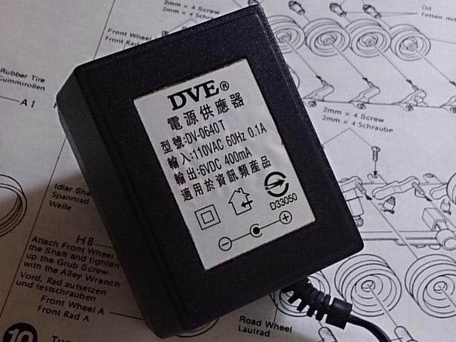
Q:
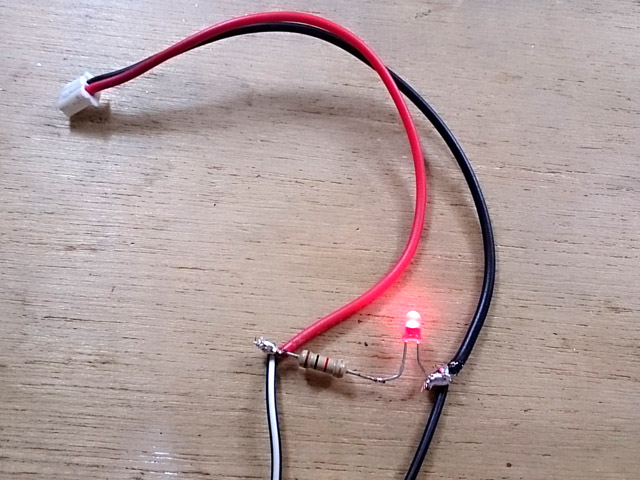
How to avoid damage that caused by short circuit to the board? A:Damage can be prevented by using a current limited power
adaptor as power source, first to find a ~6V, 400mAh power adaptor, 1K 1/4W ohm
resistor, LED and a motor cable(from HL cable Set)
then
connect + wire(with white strip) from adaptor to red wire of HL cable, - wire to
black wire of HL cable, adn wire resistor and LED as the following to act as
indicator.
Each
time, when you did some modification on circuit or after installation, use this
as power source fist. plug connect each by each, and LED will be dimmed
immediately if any shortage in circuitry and not thing on TK board will be
damaged because power can only supply low & limited current.
The
board might be act very strange when it's power by this, such as motor can not
moves will, cannon fired unexpectedly when turret rotation sound comes up, these
are quite normal because current is not enough.
Q: All function runs but just no sound!!
A:
This can be the
common issue on HL Volume Control
board, just to short outer pins of CN4 with
tweezers to verify it. if
sound comes out when doing this, the HL volume control board is broken.
Q:Tank
moves backward faster than forwards and does not turn. It only turn if firstly
turn steering stick and secondly throttle stick.
A: To turn off mixer on transmitter and test
again.
Q:Can get motor
sounds, cannon sounds, turret sounds, but no motion on either drive motors or
turret rotation gearbox
A: Check if battery voltage
is too low, auto cutoff function cuts motor off when battery voltage is too low.
Q:It
is possibleto change the
sound?
A:No, to change
sound on TK board required some equipment and technique, so you can not do it by
yourself, but we can if you send us processed
sound file(22KHz, 8-Bit format) that you want
to program into,
average lead time is 2 weeks, This service is free of charge with MOQ( Minimum
order quantity) of 3 units.
The following are the sound effect section you can change.
A: A piece of software
that convertsRudder and
Throttlecontrol signalto Left and
Right track speed signal. All TK board has mixer on it, mixer
function on RC transmitter need to be turned off.
Q:What is Safety shutoff:
A:
Controller cuts motor off and waits signal come back.
Q:What is Auto cutoff:
A:The motor cutoff will
occurred when battery input drops below minimum supply voltage of controller.
Q: Which RC system can works
with TK board:
A:Basically, TK can work with all kind of aftermarket RC system
as long as it's PWM system, here is a table list most popular one.
Brand
Band
Model Number
Result
Futaba
72M
T4VF
OK
Futaba
27M AM
4WD
OK
Futaba
2.4G
T4YF-2.4G
OK
TURNIGY
2.4G
9X
OK
Spektrum
2.4G
OK
PLANET
2.4G
OK
FlySky
2.4G
FS-CT6B
OK
( Need
to turn mixer function on transmitter off )
Hobby
King
2.4G
HK T6A
OK
Perfex
2.4G
M24-H radio
OK
Tactic
TTX
TTXseries
OK
JR
27M
OK
Q: Audio Amp thermal
protection:
A:
that turns off device when junction temperature over 150 degree C to prevent
damage
Q:
Is it possible to make additional settings using
existing IR signalsfor example to make
HL IR
signal and 9 hits can take, originally 5 hits?
A:
yes, IR code to receive, IR code to transmit, preset
& battle data can be set
independently.
Q:
Is it possible to set setting with other device
(not SONY IR code remote)?
A:Only Sony IR code remote can be used, you can also
have universal remote and configure it to SONY mode.
Q:Any Other
SONY remote, such as SONY Bravia unified TV
remote, can config TK20? A:
Can't sure, with more and more
setting function are added, some code not common on every remote are used. so we
suggest to use same remote as we use.
Q: What's BEC
A:BEC stands for
battery elimination circuit. This circuit powers the
receiver thought channel cable, no
secondarybattery source is required.
Precaution
Use dry battery or power supply as
power source at testing to keep burn down anything if any error on modification.
then use chargeable battery when every function working normally.
Read
carefully and fully understand the instructions before commencing assembly.
Metal
part on FET can not be touched with any metal when TK board is operating.