Turn
your V5.3 and earlier Henglong tank into proportional radio control and
decent sound in 10 mins.
Overview
TK6.0 series controller uses 4-CH conventional
PWM or 10-CH S.BUS RC system to control R/C tank's forward/backward movement, sharp
turning, pivoting, turret rotation and gun barrel evaluation at variable speed
Plug and Play for Henglong
V5.3 and earlier
Ultrasonic ESC*3 for two track motor and
turret rotation
Carefree reversing
Ultra Low turn-on resistance
FET for track motor ESC
22KHz, 8-bit high quality sound with digital sound mixer
Maximum of 5 channel of sound track, main gun,
machine gun, turret rotate, gun barrel elevation and engine sound can be
generated at the same time
3W
sound output power
0.8A BEC
EPM*2
for gun elevation(EPM1) and turret rotation/gun traverses(EPM2)
Wide operating voltage rage, from 7.2 to 12V, support 3S
Li-Po battery
Support air-soft gun with sound synchronization
Support TAMIYA IR battle code
Support
RealRecoil servo port
Safety shutoff prevents unwanted movement while signal lost
Auto R/C signal detection
Miniature design(60mm X 50mm X 20mm) for 1/25~1/16 R/C Tank
V1
Engine Sound Simulation
Variants
Device
TK6.0
TK6.1
TK22
Remote Control System
Traditional 4-CH AM, FM or 2.4G RC system
2.4G RC system
with
S.BUS
Traditional 4-CH AM, FM or 2.4G RC system
Control
Scheme
4-CH
S.BUS 10-CH
4-CH
TAMIYA IR battle
Compatible
YES
YES
YES
Cannon
Reload Time
3, fixed
3, fixed
Programmable
Lives
6, fixed
6, fixed
Programmable
HL IR battle
Compatible
NO
NO
YES
VsTank IR
battle
Compatible
NO
NO
NO
TAMIYA 1/35
IR battle Compatible
NO
NO
NO
Damage Simulation
on track
NO
NO
YES
Damage Simulation
on turret
rotation and gun elevation
NO
NO
YES
Long range IR battle
(>30M)
YES
YES
YES
Engine Sound
Simulation
V1
V1
V1
Neutral Gear
NO
NO
NO
Sound set for
specific tank model
>20 types
>20 types
>20 types
Track driver
Current
20A/60A*
20A/60A*
20A/60A*
Track driver
Momentum Effect
with ON/Off Control
NO
NO
YES
Turret Rotation Speed Control
YES
YES
YES
Gun Elevation Speed Control
YES
YES
YES
Gun Elevation
Servo Port
NO
YES
YES
AUX Power/Motor Control
NO
YES
YES
2nd MG sound and Light
effect
NO
NO
NO
AirSoft with Sound Synchronization support
YES
YES
YES
HL Recoil
Unit support
NO
NO
YES
TAMIYA Recoil Unit Support
NO
NO
YES
Smoker driver
YES
YES
YES
Proportional
Smoker driver
No
No
No
Head Light on/off control
YES
YES
YES
Tank Personalization
YES,Simplified
YES,Simplified
YES
LED GUN FLASHER Port
YES
YES
YES
Chassis
Recoil On/Off
Control
YES
YES
YES
Auto Load
Position
NO
NO
NO
Engine Deck
Level Detection
NO
NO
NO
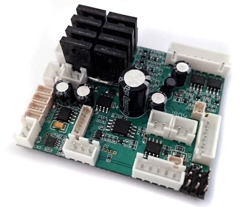
Kit contained
TK6.0 board*1,
RX
cable*4
TK6.0S board*1,
RX
cable*1
TK22 board*1,
RX
cable*4
Price
(USD)
$50
TBD
$90~110
Release Schedule
2019, July
TBD
Released
* W variant
Side-By-Side Comparison with Henglong TK6.0
CLARK
Henglong
6.0
6.0
Remote Control System
Standard PWM/ S.Bus Hobby RC
Proprietary 2.4G
ELECTRICAL CHARACTERISTICS
Max. Track driver
current
20/60A
60A
Max. turret/gun
elevation driver
current
7A
2A
IR Battle Related
TAMIYA IR Code
YES
YES
Fire rate
3 seconds, fixed
3 seconds, fixed
Lives
6, fixed
6, fixed
Re-birth time
6 seconds, fixed
??
Damage Simulation on track speed
NO
NO
Track
Recoil Strength Adjustment
YES, 8 Level
YES, 3 Level
Sound Effects Related
Seamless
Mxer
YES
No, engine sound restarted when other
sound effect is palyed
built-in
Sound set
1,
More then 20 tanks sound sets can be selected
4, fixed
Incoming sound
Yes
??
Reload sound
Yes
??
Audio
Amplifier
3W
??
Peripherals
Servo
Recoil
NO
NO
Servo Elevation
NO
NO
Price
Listed Price
$50 for board
$42 for board,
$40 for transmitter
Side-By-Side Comparison with Henglong TK6.1
CLARK
Henglong
6.1
6.1
Remote Control System
Standard PWM/ S.Bus Hobby RC
Proprietary 2.4G
ELECTRICAL CHARACTERISTICS
Max. Track driver
current
20/60A
60A
Max. turret/gun
elevation driver
current
7A
2A
IR Battle Related
TAMIYA IR Code
YES
YES
Fire rate
3 seconds, fixed
3 seconds, fixed
Lives
6, fixed
6, fixed
Re-birth time
6 seconds, fixed
??
Damage Simulation on track speed
NO
NO
Track
Recoil Strength Adjustment
YES, 8 Level
YES, 3 Level
Sound Effects Related
Seamless
Mxer
YES
No, engine sound restarted when other
sound effect is palyed
built-in
Sound set
1,
More then 20 tanks sound sets can be selected
4, fixed
Incoming sound
Yes
??
Reload sound
Yes
??
Audio
Amplifier
3W
??
Peripherals
Servo
Recoil
YES
YES
Servo
Recoil
direction reverser
YES
??
Servo Elevation
YES
YES
Servo Elevation
direction reverser
YES
??
Price
Listed Price
TBD
TBD
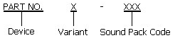
Product
Identification System
Device
TK6.0
TK6.0 Entry
Level Tank
Controller
TK6.1
TK6.1 Entry
Level Tank
Controller
Variant
Blank
Standard
S
Support S.BUS
interface
P
Sound
Programmable
G
Support
dual-axial Gun Stabilizer
W
With
preordered wire on CN1A, CN1B, CN6A, CN6B, CN7A and CN7B pads
A1
105A track
motor current
Sound Pack
T1
Tiger I
KT
King Tiger
CH2_V1
Challenger 2
ver. 1
.....
Refer to TK Sound Pack webpage for more
information
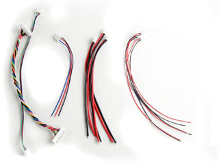
Accessories
Part Number
Description
CAB001
1.25mm pitch cable
connector for connecting IR LED or Gun Flash LED
HL Cable Set
Motor
Cable *2
Battery Cable *1
Speaker Cable *1
Smoke Unit Cable *1,
Smoke Unit Switch Cable (no
switch) *1
8P Inter-connection Cable *1
Volume Control Cable( no VR ) *1
HL Power
Cable
One end to TK20, another end to
battery, one switch in the middle
TK6.0 ECN( Engineering change
notice)
Batch
Notice/Change/New Features
Release Schedule
1st
-Initial Production
2018. Jan.
TK6.0 4-CH control
mode scheme
Booming Cannon
Cannon elevation
Turret rotation
Head
light control on/off
AUX Power on/off (Only
available when Main Gun Function Mode is
set to
Gun elevation servo Mode)
Engine sound on/off
Fire
MG: Number of burst is controlled by the time of stay.
Tank move
forward and backward
Right and
Left turn
TK6.0S 10-CH S.BUS control
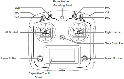
mode scheme( Based on FS-i6S transmitter + FS-iA10b/6b Receiver )
Transmitter: FS-i6S, self-centering VrA
and VrB type Radio
RX:FS-iA10b
Layout
Command
S.BUS
Channel
assignment
Tank Right
and Left turn
CH1 (Stick)
Tank move
forward and backward
CH2 (Stick)
Cannon elevation
CH3
(Stick)
Turret rotation
CH4
(Stick)
SwB: Up
SwC: Center -> Up
Natural Gear Shift In/Out
Assign SwB to CH7
Assign SwC to CH8
SwB: UP
SwC: Center -> Down
Engine start/stop
Assign SwB to CH7
Assign SwC to CH8
SwB: Center
SwC: Center -> Up
NA
Assign SwB to CH7
Assign SwC to CH8
SwB: Center
SwC: Center -> Down
NA
Assign SwB to CH7
Assign SwC to CH8
SwB: Down
SwC: Center -> UP
NA
Assign SwB to CH7
Assign
SwC to CH8
SwB: Down
SwC: Center -> Down
Head
light On/Off
Assign SwB to CH7
Assign SwC to CH8
SwA
UP: Smoke
Unit On
DW: Smoke
Unit Off
Assign SwA to CH5
SwB
NA
Assign SwB to CH6
VrA
UP: Booming Cannon
MID:
DW: MG1
Assign VrA to CH9
VrB
UP:
MID:
DW:
MG2
Assign VrB to CH10
Specification
Parameter
Unit
Maximum current of track ESC
20
A
Maximum current of turret and
cannon elevation ESC
6
A
Maximum current of Smoker Driver
6
A
Maximum supply
voltage
7.4
V
Minimum supply
voltage
7.2
V
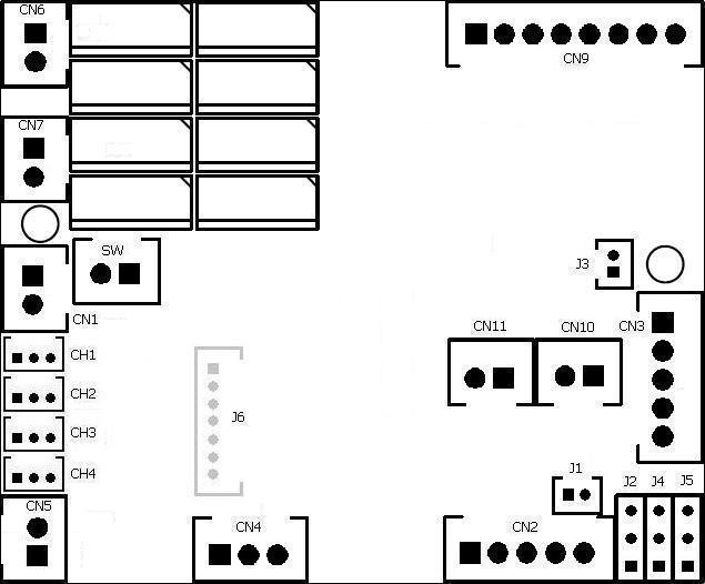
TK6.0 series connector layout
Connection diagram( Click to download full size
image )
TK6.0 and 6.1 connector and pin assignments(Text
in red is the modification required for HL TANK)
Connector
Description
TK6.0
TK6.0S
SW
Switch Cable Port
HL tank already have power switch on battery cable path, so
additional switch is no longer required, just to short
pins in this port by jumper or connect to a switch cable and keep it switched
on.
CN1
Battery Power
1. Battery +
2.
Battery -
CN2
IR Prog/
Track Recoil Control
1.
IR Programming receiver +
2.
IR Programming receiver Signal
3.
IR Programming receiver -
4. IR Programming Indicator LED -
5. IR Programming Indicator LED +
*To
disable track recoil, short Pin 2 & Pin 3 by a Jumper
CN3
Gun
Flash Port
1. Battery +
2.
Strobe Trigger
3.
Battery -
4. AirSoft/Recoil Switch
5. AirSoft/Recoil Switch
CN4
Sound
Volume
1.
Volume Signal
Output (
Wiper pin of VR
)
2. Battery -( 1 outside pin of
VR )
3.Volume
Signal
Input (
1 outside pin of VR )
CN5
Speaker
1.
Speaker -
2.
Speaker +
CN6
(*1)
Motor Left
CN7
(*2)
Motor
Right
CH1
Steering control signal:
Futaba: CH1
JR:AILE
S.BUS input
1. Battery -
2. +5V
3. Signal
CH2
Throttlecontrol signal
Futaba:
CH2( Mode 2)
Futaba:CH3 ( Mode 1 )
JR:ELEV
MG2 LED:
1. Not Connected
2. LED +
3.
LED -
CH3
Multi function control signal 1
Futaba:
CH3( Mode 2)
Futaba: CH2(
Mode 1 )
JR:THRO
CH4
Multi function control signal 2
Futaba: CH4
JR:RUOD
CN9
Upper
Hull Functions
(
Turn, Lift, Shoot, Light)
1. Machine gun LED-
2. Head Light LED-
3. Machine gun LED+,
Head Light LED+ &
AIRSOFT/RECOIL Motor+
4. AIRSOFT/RECOIL Motor-
5. GUN ELEVATE MOTOR(*4)
6. GUN ELEVATE MOTOR(*4)
7. TURRET MOTOR(*3)
8. TURRET MOTOR(*3)
CN10
Smoke
Unit
CN11
Smoke
Unit Switch
J1
NA
NA
J2
(*5)
RealRecoil Servo Port
RealRecoil Servo Port is always
turned ON, no setting is needed to turn it on
1. Signal( White Wire)
2.
+5V ( Red Wire)
3. Battery - (Black Wire)
See
RealRecoil section in Assembly Guide
J3
LED Main Gun Flasher Port
1. Main Gun
LED +
2. Main Gun
LED -
J4
(*4)
NA
NA
J5
(*3)
NA
NA
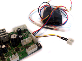
Installation Guide
Disconnect RX-18 and plug cables to the same connector on TK board,
Set
Sound Volume to middle
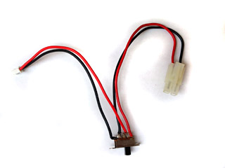
Install
a switch cable (for example, HL Smoke Unit Switch Cable)
to SW connector( Switch Cable Port)
as power switch.
Because HL tank already have power switch on battery cable path, so additional
switch is not required, just to use a jumper to short
pins in SW Cable port or connect a switch cable and keep it switched on.
When high current track motors are used, such as 400/480 motor,
power switch on battery cable path will not be able to handle,
connect a switch cable (for example, HL Smoke Unit Switch Cable)
to this port
as power switch.
Connect
channel cables to receiver according to RC
mode( See picture "TK series connector and pin assignments" ) . if you are not sure what mode you RC system is, just swap CH2 and CH3 and
try again.
TK20 board has BEC( Battery
eliminate
circuit),
can power receiver through channel cables, no additional battery is needed for
receiver
Set CH1,
2 and 3 trimmer on transmitter to center position, Set CH4 trimmer on
transmitter to most left or right position,
Connect power adaptor( See FAQ )
Switch on TK board and transmitter, you should hear
turret traverse
sound. if not, please contact us.
gently
move CH4(Multi
function control signal 2)
trimmer to center till
turret traverse is gone.
gently
move CH2(Throttle )
trimmer up and down if you hear motor hum sound.
Cannon
firing sound should be generated and
recoil servo should moves when move
CH3 stick to most top position, if not, gently move CH3(Multi
function control signal 2 )
trimmer up and down till
it work correctly.
You are
all set
Disconnect power adaptor and connect battery( make sure that battery is fully
charged).
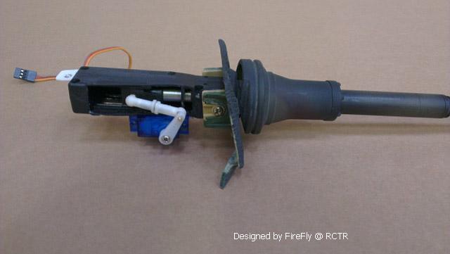
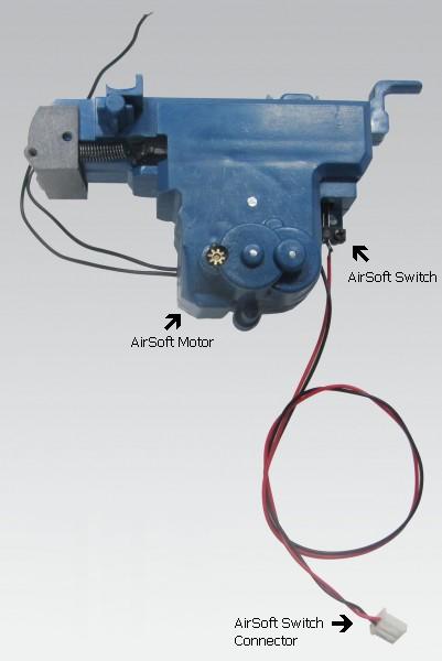
In HL original design, gun
Elevation and AirSoft sharing same driving H/W, so the gun elevation can only be
controlled in one direction, if you missed the angle you want, you will
need to wait a full cycle of gun elevation, to correct this problem, we add
dedicate AirSoft control h/w to TK20 board. the following shows you how to
correct HL tank and get two direction elevation.
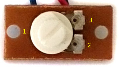
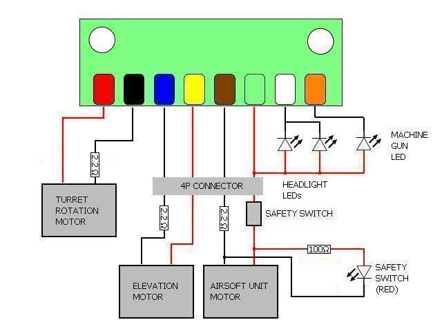
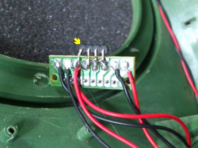
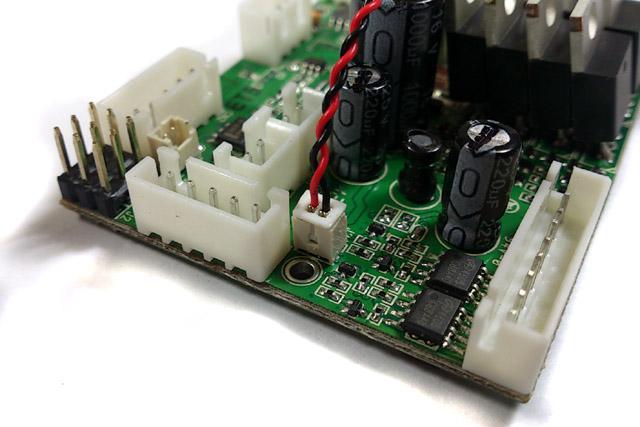
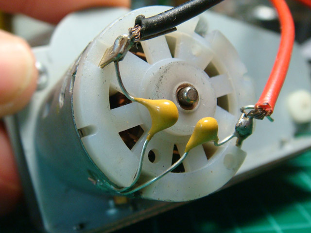
The
picture below is original wiring in HL tank:
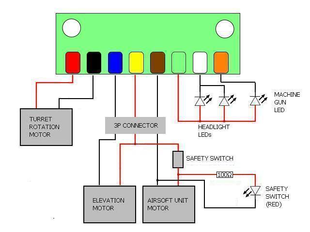
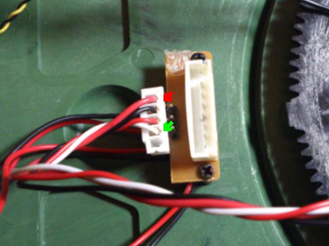
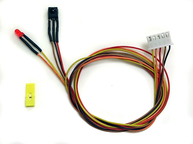
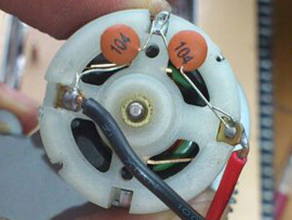
Modify
it as the following:
Green
box in the diagram above represent the small PCB in tank, small red,
black, blue ... orange in it represent the wire color.
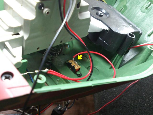
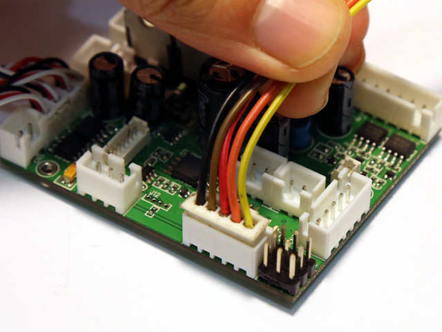
1.
Disconnect red wire between safety switch and gun barrel elevation unit.
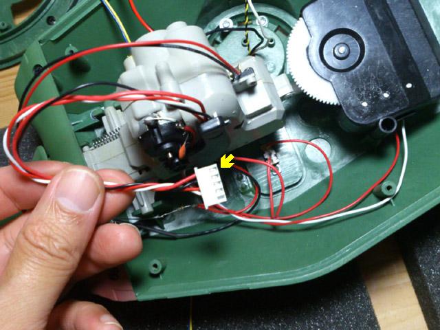
2.
Change original 3P connector to 4P type, add additional wire from safety switch
to 4P connector,
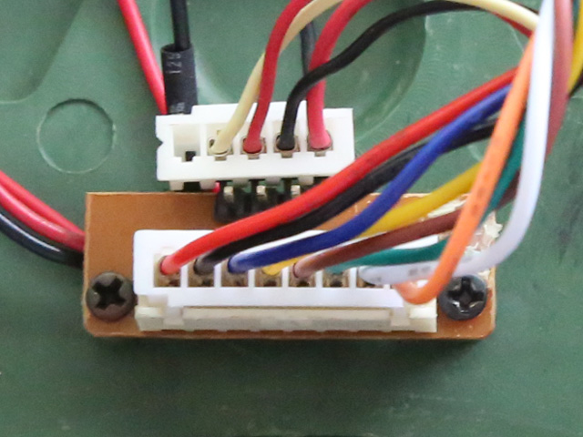
3. Add
4P connector HUL-8P PCB connector
4.
AirSoft unit is now controlled by red-black pair, gun barrel unit is
controlled by red-white pair. and you can connect 8P connector to CN9 on
TK-18/20 with original cable.
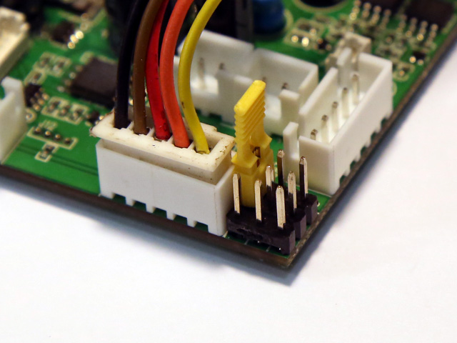
5(Optinal). refer to wiring diagram, wire a 2.2 ohm
1/2W (color code: red read gold gold) in-serial resistor to turret rotate, elevation and airsoft motor
to limit the current to protect FETs on TK22 in case you stall motor.
2.2 ohm resistor can also be found on RX-18.
Here is a video of airsoft setup for Taigen
Tank
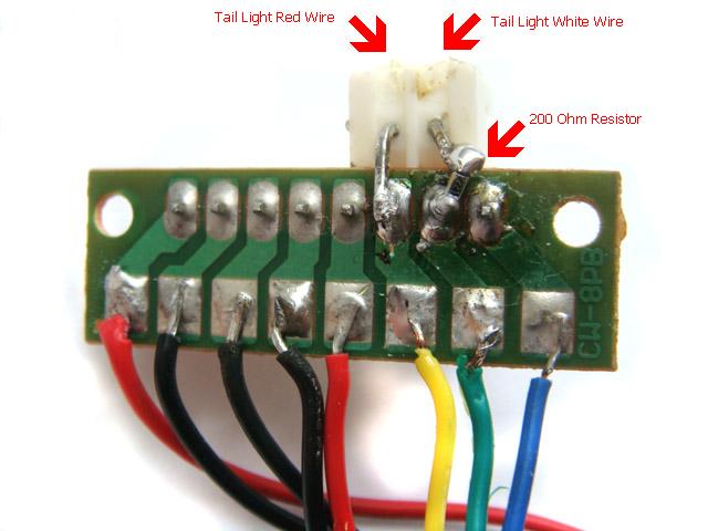
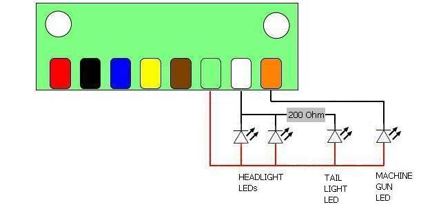
HL Tail Light Correction
Tail
Light in HL tank is wire to MG light, so the Tail Light flashes when MG firing,
this is very funny to us, to correct this problem and make tail light to be
controlled with Headlight, please refer to the picture below and rewire it.
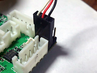
1. Remove 2 pin plug from PCB, twist angled
pins to opposite side,
2.
Connect Tail Light LED + pin( Red wire of Tail Light cable) to CN9.3 pin(
Yellow wire )
3.
Connect a 200 Ohm resistor between 2-P connector pin and CN9.2 pin(Green), a SMD
type resistor is used in this example to save space.
Original wiring
diagram
Corrected wiring
diagram
RealRecoil(
Patent Pending)
servo port allows you to recreate real gun barrel recoil movement with single &
cheap servo, what you need to do is to link servo and gun barrel then RealRecoil takes
the rest. direction of servo movement can be set by user, please see section "Tank
Personalization"
GUN FLASHER Installation
HL Hop-up options "HIGH-TENSION
FLASHER" can be easily installed and works with TK20 to simulate gun nuzzle
flash when firing.
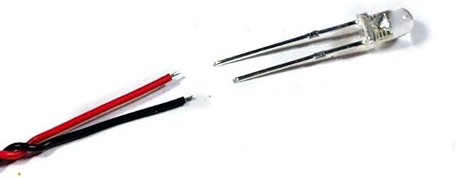
LED GUN FLASHER Installation:
A white LED and cable connector are needed( Part Number
is F003)
Solder color wire (red wire in
this example) to long pin of white LED, black wire(-) to short pin,
Plug cable into J3.
Tank
Personalization( Patent Pending)
Settings
of TK series board can be changed by
Configuration IR REMOTE
as IR command transmitter, and TAMIYA battle unit(TBU),
Heng-Leog battle
unit(HBU), or our programming line as IR command receiver.
Steps
to change settings:
STEP 1: Turn power off, Turn power off, Turn power off,
STEP 2: Plug programming line/TBU/HBU
through TBU/HBU base into
CN2 Infrared Port ,
STEP 2: Install a jumper to J2
as shown below, Turn power on,
STEP 4:Refer to function table listed below,
point
Configuration IR REMOTE to
TBU/HBU/Programming line receiver, and press the
button
of setting that you want to change,
"*"
sign in
function table means
the default setting that is programmed in factory
STEP 5: Indicator on
TBU/HBU flashes according to new
setting value.
STEP 6:
turn power off, remove
jumper on J2, then turn power on and TK board runs
with new settings.
Function tables:
Save
current setting to
PRESET 1: Press number
key "1" on IR Configuration Remote to save,
Available Settings
Indicator
flashes times
Description
Save to PRESET 1
1
Indicator flashes when setting
is saved
Save
current setting to PRESET 2: Press number
key "2" on IR Configuration Remote to save,
Available Settings
Indicator
flashes times
Description
Save to PRESET 2
2
Indicator flashes when setting
is saved
*Once
you've adjusted everything, you can
push "1" or
"2" to save
current setting to PRESET 1
or 2. If you don't do this saving the board remembers
the last settings.
Use saved settings:
Press "ENT" or "SOUND MODE" Key on
IR Configuration Remote to select.
Available Settings
Indicator
flashes times
Description
Use PRESET 1
setting
1
UsePRESET 2 setting
2
Use Factory Default Setting
( Read-Only )
3
To
restore factory
default value in case of setting data is messed up.
*To
switch between the presets you press either "sound
mode" or "enter" button, once the preset is selected,
switch tank off and remove setup jumper. Switch back on and away you
go.
Mixer Mode:
Press
(MUTE) key on IR Configuration Remote to select.
Available Settings
Indicator flashes times
Description
Mixer Mode
1
1*
Tank mode 1
CH1 controls
rudder, CH2
controls throttle.
Proportional steering,
sharp and pivot turn* are supported
Left Track
Right Track
Pivot
Turn
Sharp
Turn
Proportional
Steering
Proportional
Steering
Sharp
Turn
Pivot
Turn
Mixer Mode
2
2
OFF mode
CH1
controls left track, CH2 controls right track
When
using triple differential gear box,
CH1
controls steering motor(CN6),
CH2
controls propulsion motor(CN7)
Mixer Mode
3
3
Tank mode 2
CH1 controls
rudder, CH2
controls throttle,
Proportional steering and
sharp turn are supported
Left Track
Right Track
Sharp
Turn
Proportional
Steering
Proportional
Steering
Sharp
Turn
Mixer Mode4
4
Half-Track mode
CH1 controls
rudder, CH2
controls throttle,
Support proportional steering only.
Max. turn
ratio ( speed ratio of left and right track at hard left and right turn)
can be
configured form large (4)
to small (8)
Left Track
Right Track
Proportional
Steering
Proportional
Steering
Mixer Mode
5
5
Mixer Mode
6
6
Mixer Mode
7
7
Mixer Mode
8
8
*pivot
turn is also named as super spin.
Momentum effect On/Off: Press "SLEEP(0x36)"
or ""
on IR Configuration Remote to select
Available Settings
Indicator
flashes times
Description
Off
1*
ON
2
*This function
is only available on TK22
Reload Sound On/Off: Press "Timer
Off(0x3C)"
or "
"on IR
Configuration Remote to select
Available Settings
Indicator
flashes times
Description
On
1*
Off
2
*This function
is only available on TK22
Firing
tank gun hullrecoilOn/Off: Press "SURROUND(0x29)"
on IR Configuration Remote to select
Available Settings
Indicator
flashes times
Description
On
1*
Off
2
*This function
is only available on TK22
Strength of
firing tank gun
hullrecoil:Press
"VOL UP" key on
IR Configuration Remote
to select
Available Settings
Indicator
flashes times
Description
1
1
Small( 1 ) to Large( 16
)movement
:
:
6
6*
:
:
16
16
RealRecoil servo direction:
press "CH down"
or "PROGR -" key
on IR Configuration Remote to select
Available Settings
Indicator
flashes times
Description
Normal
1*
Reversed
2
FAQs
Q:
Airsoft unit fires continuously and have no cannon sound.
A:When main Main Gun
Function Mode is configured to AirSoft
Mode, TK22/20 start to drive AirSoft motor (thought CN9 3rd &4th pin) when fire
cannon command is received.
when Airsoft just fired, Airsoft switch is closed , Tk22 knows it thought CN3 Pin4
& Pin5.
and then stop to drive Airsoft Motor and start to generate cannon. So in order
to make it works properly, AirSoft motor need to be connected to CN9 pin3
and pin4. AirSoft switch connector to CN3 Pin4
& Pin5.
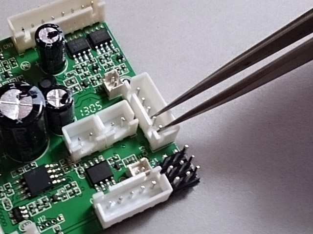
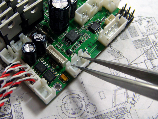
You can
simply test it by a
tweezers, to short and release
it will stop AirSoft motor.
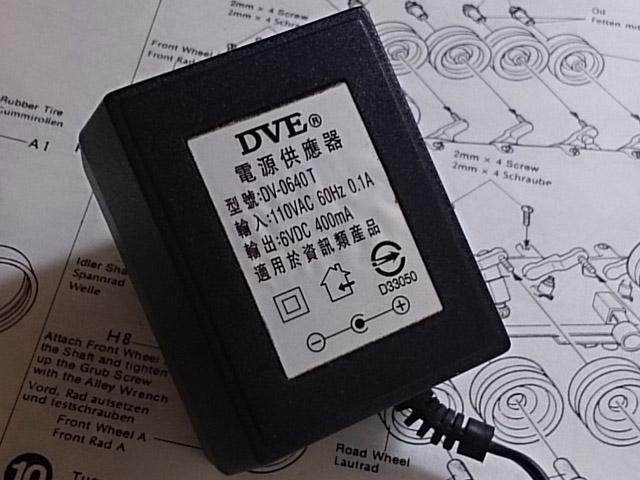
Q:
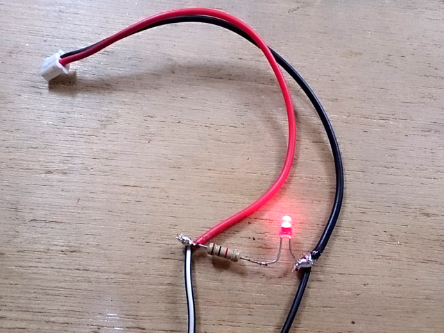
How to avoid damage that caused by short circuit to the board? A:Damage can be prevented by using a current limited power
adaptor as power source, first to find a ~6V, 400mAh power adaptor, 1K 1/4W ohm
resistor, LED and a motor cable(from HL cable Set)
then
connect + wire(with white strip) from adaptor to red wire of HL cable, - wire to
black wire of HL cable, adn wire resistor and LED as the following to act as
indicator.
Each
time, when you did some modification on circuit or after installation, use this
as power source fist. plug connect each by each, and LED will be dimmed
immediately if any shortage in circuitry and not thing on TK board will be
damaged because power can only supply low & limited current.
The
board might be act very strange when it's power by this, such as motor can not
moves will, cannon fired unexpectedly when turret rotation sound comes up, these
are quite normal because current is not enough.
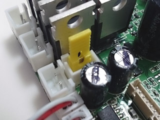
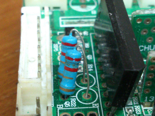
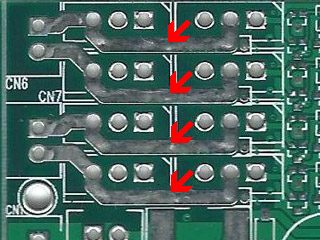
Q:
I accidentally shorted speaker wire and now had barely any sound, everything
still works but hardly any sound. A:A FB( pointed by red arrow) might be damaged because of
over current, please remove it and short its two pads by solder or wire. Of
course, It's the best if you can find a 200 ohm FB and replace the broken one.
2nd,
the audio amplifier ( pointed by green arrow) goes very hot when operating, do
not apply glue or double faced adhesive tape on it and left some space for it
for heat dissipation.
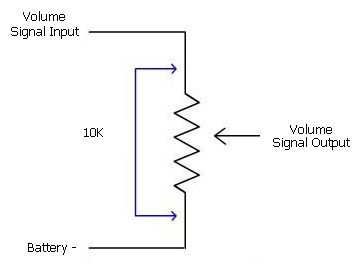
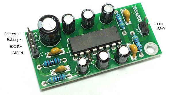
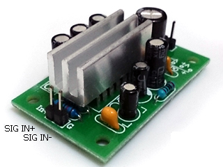
Q:
How to interface to 6W external sound booster(amplifier) A:This picture shows the pin
assignment of
external 6W amplifier, in this example, Battery + & Battery - are power input pin,
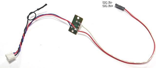
SIN+ and - is for audio signal input, SPK+ and - is speaker port
First
to disconnect black wire from HL Volume control board and isolate it with tape,
wire a 2-P, 2.54mm pitch connector wire to Volume control board as shown below
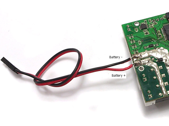
Then
to power amplifier by battery
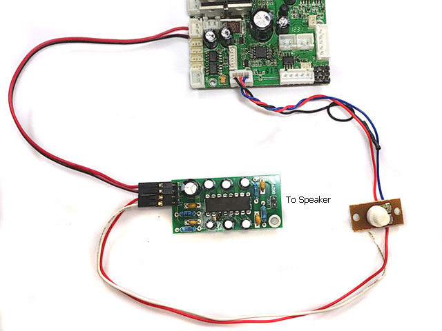
Finally, connect power form TK22 to Battery+ & Battery - pin, connect 2-P, 2.54mm pitch
connector wire SIG+ and SIG-,and then connect sparker to SPK+ and SPK- pin.
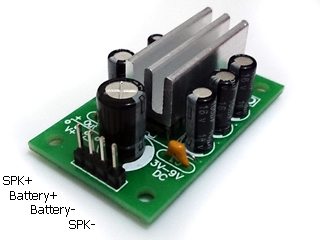
Here is pin assignment of
another type 6W AMP, just refer to the above and wire pins with same pin assignment.
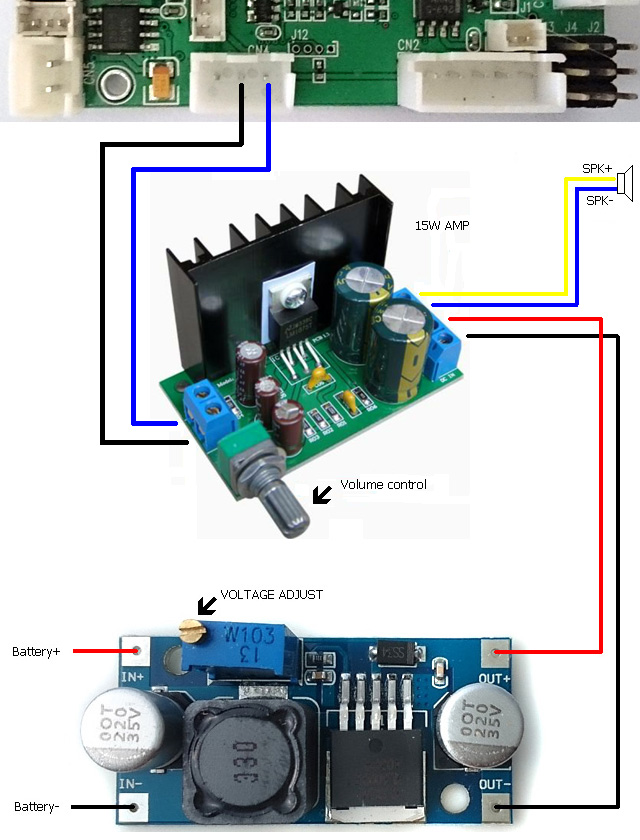
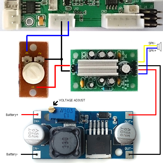
Generally, higher the input power, higher the sound output power on speaker, so
we can also use a DC-to-DC voltage booster to convert battery voltage into
higher voltage, then to drive external audio amplifier to have more solid and
powerful sound,
Because output ripple is much lower after
DC-to-DC conversion, so this can also reduce motor "humm" sound during motor
start up and at low speed. another
benefit of this configuration is that you can use 8-ohm speaker but still have
good loudness. In
the example below, we use an adjustable DC-to-DC voltage booster
to convert battery voltage into 12V.
Step 1: first to connect AMP to
TK board and battery as describe previous and make sure it sounds correctly,
Step 2: connect
DC-to-DC voltage booster to
battery only, measure theoutput voltage,
if voltage is higher or less than
12V, adjust VR on it till output voltage is around 12V, Step 3: disconnect AMP from
battery power then connect to the output
of
DC-to-DC voltage booster.
HINT:
use VR pointed by black arrow in this diagram to adjust voltage to 12V before
powering amplifier
Wiring diagram
for 15W amplifier:
Use VR on DC/DC converter to set output voltage to
15V
Q:
When I move left stick backward, only the right track goes backward the left
track does not move, It is possible I crossed the +positive and --negative
terminals when connecting the new motors? A:
Yes, when +positive and --negative
terminals are crossed, one of terminal will burn out immediately, you can bend
FETs a little bit to check these traces, one of them should be broken. you can
reconnect it by soldering to fix the problem.
We recommend that to use power adapter(7.2V, 400mAh) as power
source after rewiring. then switch to battery when everything are tested OK.
Q: Tank hull
recoil movement direction is not correct, moves forward and then backward while
firing main gun. A: Just need to swap motor cables, CN6 to Motor
Right, CN7 to Motor Left, and turn on servo reverser function on throttle
channel from radio transmitter.
Q: All function runs but just no sound!!
A:
This can be the
common issue on HL Volume Control
board, just to short outer pins of CN4 with
tweezers to verify it. if
sound comes out when doing this, the HL volume control board is broken.
Q: Do I need noise filtering capacitor on motor
A:
Yes, it's needed to prevent back EMF to interference TK20 board. All HL stock
tank already have it on motors
This type of capacitor is not good, DO NOT USE!
Q:Tank
moves backward faster than forwards and does not turn. It only turn if firstly
turn steering stick and secondly throttle stick.
A: To turn off mixer on transmitter and test
again.
Q:Can get motor
sounds, cannon sounds, turret sounds, but no motion on either drive motors or
turret rotation gearbox
A: Check if battery voltage
is too low, auto cutoff function cuts motor off when battery voltage is too low.
A: A piece of software
that convertsRudder and
Throttlecontrol signalto Left and
Right track speed signal. All TK board has mixer on it, mixer
function on RC transmitter need to be turned off.
Q:What is Safety shutoff:
A:
Controller cuts motor off and waits signal come back.
Q:What is Auto cutoff:
A:The motor cutoff will
occurred when battery input drops below minimum supply voltage of controller.
Q: Which RC system can works
with TK board:
A:Basically, TK can work with all kind of aftermarket RC system
as long as it's PWM system, here is a table list most popular one.
Brand
Band
Model Number
Result
Futaba
72M
T4VF
OK
Futaba
27M AM
4WD
OK
Futaba
2.4G
T4YF-2.4G
OK
TURNIGY
2.4G
9X
OK
Spektrum
2.4G
OK
PLANET
2.4G
OK
FlySky
2.4G
FS-CT6B
OK
( Need
to turn mixer function on transmitter off )
Hobby
King
2.4G
HK T6A
OK
Perfex
2.4G
M24-H radio
OK
Tactic
TTX
TTXseries
OK
JR
27M
OK
Q: Audio Amp thermal
protection:
A:
that turns off device when junction temperature over 150 degree C to prevent
damage
Q:
Is it possible to make additional settings using
existing IR signalsfor example to make
HL IR
signal and 9 hits can take, originally 5 hits?
A:
yes, IR code to receive, IR code to transmit, preset
& battle data can be set
independently.
Q:
Is it possible to set setting with other device
(not SONY IR code remote)?
A:Only Sony IR code remote can be used, you can also
have universal remote and configure it to SONY mode.
Q:Any Other
SONY remote, such as SONY Bravia unified IR
Configuration Remote, can config TK20? A:
Can't sure, with more and more
setting function are added, some code not common on every remote are used. so we
suggest to use same remote as we use.
Q: What's BEC
A:BEC stands for
battery elimination circuit. This circuit powers the
receiver thought channel cable, no
secondarybattery source is required.
Precaution
Use dry battery or power supply as
power source at testing to keep burn down anything if any error on modification.
then use chargeable battery when every function working normally.
Read
carefully and fully understand the instructions before commencing assembly.
Metal
part on FET can not be touched with any metal when TK board is operating.