|
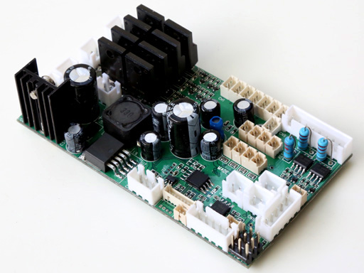
MFK-02 Series RC Excavator
Controller |
MFK-02,
a highly integrated RC Excavator controller,
for
upgrading BRUDER excavator
into proportional radio control with Light and Sound Effect

 MFK02 series controller uses
8 channels/10-CH S.BUS RC system to control R/C Excavator
60A motor driver
High quality sound with digital sound
mixer
10W
sound output power
Safety shutoff prevents
unwanted movement while signal lost
Auto R/C signal detection, suitable for 27M, 72M and 2.4G RC system MFK02 series controller uses
8 channels/10-CH S.BUS RC system to control R/C Excavator
60A motor driver
High quality sound with digital sound
mixer
10W
sound output power
Safety shutoff prevents
unwanted movement while signal lost
Auto R/C signal detection, suitable for 27M, 72M and 2.4G RC system
|
|
MFK-02S |
MFK-02 |
|
Remote Control System
|
10-CH S.BUS 2.4G RC system |
Traditional 4-CH AM, FM or 2.4G RC system |
|
Engine Sound rendering
|
Multi
Simple Set,
Fuzzy Logic Engine Sound Simulation |
Multi
Simple Set,
Fuzzy Logic Engine Sound Simulation |
|
Motor driver Current
|
60A ( 540 Motor) |
60A ( 540 Motor) |
|
Kit contained |
MFK-02S board *1,
S.BUS cable*1 |
MFK-02 board *1,
channel cable*8 |
|
Reference Price |
TBD |
TBD |
|
Product
Identification System |

| Device |
MFK-02 |
MFK-02
excavator
controller |
| |
|
|
|
Variant |
Blank |
Standard,
Equal to P Variant in TK60 series
|
| |
S |
Support S.BUS
interface |
| |
P |
Sound
Programmable |
| |
|
|
|
Sound Pack |
CAT |
CAT |
| |
|
|
| |
|
|
| |
|
|
|
MFK-02S
10-CH S.BUS control scheme( Based on FS-i6S transmitter +
FS-iA10B Receiver ) |
Transmitter: FS-i6S, self-centering VrA
and VrB type Radio
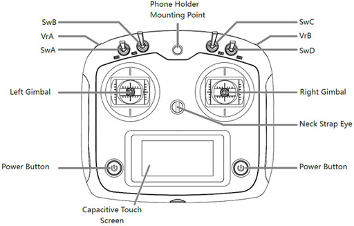
RX:FS-iA10B
|
Layout |
Command |
S.BUS
Channel
assignment |
|

CH2
CH1 |
Close/open bucket
 |
CH1 (Stick)
To do: pass to servo port |
|

CH2
CH1 |
Dipper In/Out

|
CH2 (Stick) |
|

CH4
CH3 |
Raise
/ Lower boom

|
CH3
(Stick)
To do: pass to servo port |
|

CH4
CH3 |
Slew
cab left / right
|
CH4
(Stick)
To do: pass to servo port |
|
SwA/KeyA |
Horn |
Assign SwA/KeyA to CH5 |
|
SwB: Center -> Up |
Engine start/stop |
Assign SwB to CH7 |
|
SwB Center -> Down |
Rotating Light On/Off |
Assign SwB to CH7 |
|
SwC: Center -> Up |
Controlled Switch(L4) on/ff,
can used to control
|
Assign SwC to CH8 |
|
SwC: Center -> Down |
Head Light
On / Off |
Assign SwC to CH8 |
|
SwD |
UP:
Smoke Unit
On
DW:
Smoke Unit Off
|
Assign Key2 to CH6 |
|
VrA |
Left Track Control Lever |
Assign VrA to CH9 |
|
VrB |
Right
Track Control Lever
|
Assign VrB to CH10 |
|
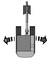
MFK-02
4-CH Control Mode and operation |
|
 |
Left Track Move forward and
backward |
|
|
 |
Right Track Move forward and
backward |
|
|

|
Horn |
|
|

|
Engine
On/Off |
|
|
 |
Head
Light On/Off |
|
|

|
Rotating
Light On/Off |
|
|
CH5 |
Boom Down/Up |
|
|
CH6 |
Dipper IN/OUT |
|
|
CH7 |
Bucket CURL/Dump |
|
|
CH8 |
Swing Left and Right |
|
|
Parameter
|
|
Unit
|
|
Maximum current of track ESC |
60 |
A |
|
Maximum current of turret and
cannon elevation ESC |
7 |
A |
|
Maximum current of Smoker Driver |
7 |
A |
|
Maximum supply
voltage |
7.4
|
V |
|
Minimum supply
voltage |
7.2 |
V |
MFK series connector and pin assignments
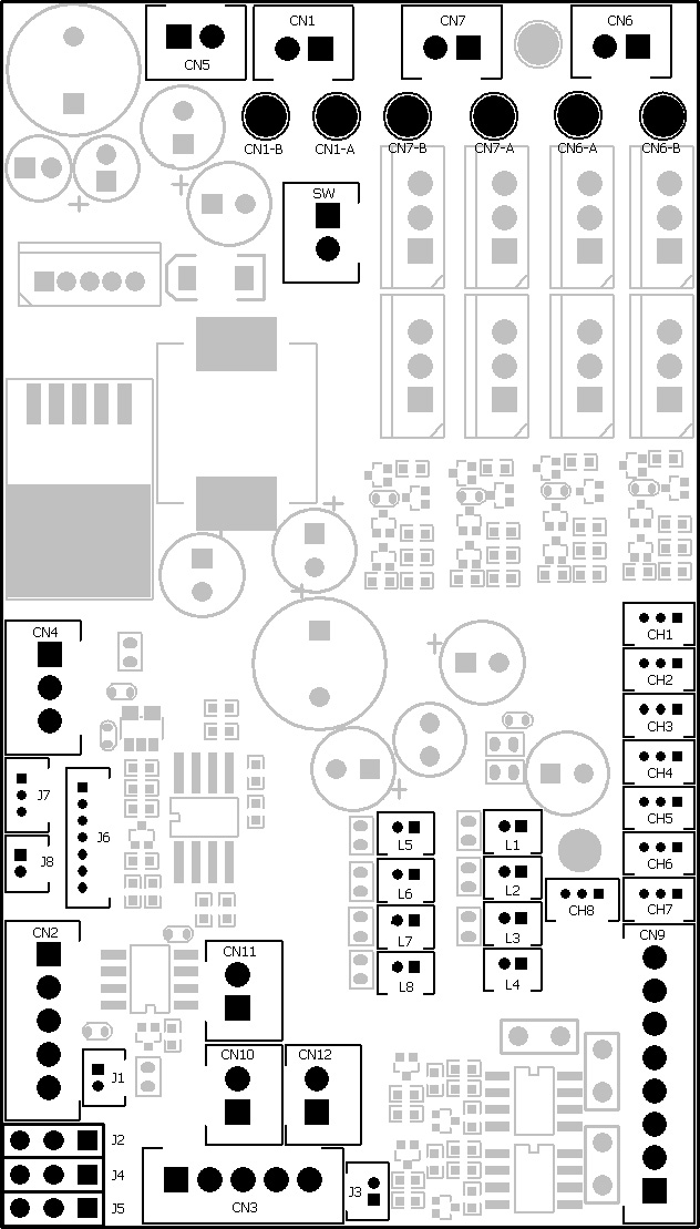
MFK-02S Pin assignment
|
Connector
|
Description
|
Note |
|
SW |
Switch Cable Port |
Connect to switch cable
|
|
CN1
|
Battery Power
|
1. Battery +
2.
Battery -
|
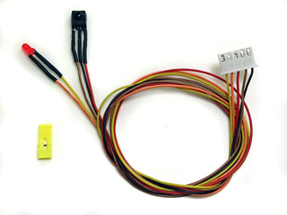
|
CN2 |
IR Configuration
Port |
1.
IR
Configuration
receiver +
2.
IR
Configuration
receiver SIG
3.
IR
Configuration
receiver -
4. IR
Configuration Indicator
LED -
5. IR
Configuration Indicator
LED +
|
|
CN3 |
NA |
|
|
CN4 |
Sound
Volume |
1.
Volume Signal
Output (
Wiper pin of VR
)
2. Battery -( 1 outside pin of
VR )
3.
Volume
Signal
Input (
1 outside pin of VR ) |
|
CN5 |
Speaker |
|
|
CN6
|
Left Track ESC
|
|
|
CN7
|
Right Track ESC |
|
|
CH1
|
|
|
|
CH2
|
|
|
|
CH3 |
|
|
|
CH4
|
|
|
|
CH5 |
|
|
|
CH6 |
|
|
|
CH7 |
|
|
|
CH8 |
|
|
|
CN9 |
Light
Effect Functions |
1.
2.
Head Light LED-
3.
Head Light LED+
4.
5.
6.
7.
Cab slew motor
+
8.
Cab slew motor
- |
|
CN10 |
NOT USED |
|
|
CN11 |
NOT USED |
|
|
J1 |
|
|
|
J2 |
Boom Servo
Port |
1. Signal( White Wire)
2.
+5V ( Red Wire)
3. Battery - (Black Wire) |
|
J3 |
|
|
|
J4 |
Dipper
Servo Port |
1. Signal( White Wire)
2.
+5V ( Red Wire)
3. Battery - (Black Wire) |
|
J5 |
Bucket
Servo Port |
1. Signal( White Wire)
2.
+5V ( Red Wire)
3. Battery - (Black Wire) |
|
J6 |
NA |
|
|
J7 |
S.BUS/TK-LINK
Port |
To
connect S.Bus Receiver
1. N/A
2.
Battery -
3.
S.BUS RX
4.
TK-LINK TX |
|
J8 |
NA |
|
|
L1 |
Rotating
Light LED1
|
1. LED +
2. LED - |
|
L2 |
Rotating
Light LED2
|
1. LED +
2. LED - |
|
L3 |
Rotating
Light LED3
|
1. LED +
2. LED - |
|
L4 |
Controlled SW/Tail Light |
When
connect to a motor:
1. Motor +
2. Motor -
When connect to a
LED:
1. 200ohm in-serial resistor --> LED +
2. LED -
Maximum Current : 7A |
|
L5 |
Head Light LED 1 |
1. LED +
2. LED - |
|
L6 |
Head Light LED 2 |
1. LED +
2. LED - |
|
L7 |
NA |
|
|
L8 |
NA |
|
MFK-02 Pin assignment
|
Connector
|
Description
|
Note |
|
SW |
Switch Cable Port |
Connect to switch cable
|
|
CN1
|
Battery Power
|
1. Battery +
2.
Battery -
|
|
CN2 |
IR Configuration
Port |
1.
IR
Configuration
receiver +
2.
IR
Configuration
receiver SIG
3.
IR
Configuration
receiver -
4. IR
Configuration Indicator
LED -
5. IR
Configuration Indicator
LED +
|
|
CN3 |
NA |
|
|
CN4 |
Sound
Volume |
1.
Volume Signal
Output (
Wiper pin of VR
)
2. Battery -( 1 outside pin of
VR )
3.
Volume
Signal
Input (
1 outside pin of VR ) |
|
CN5 |
Speaker |
|
|
CN6
|
Engine Vibration
Motor
|
|
|
CN7
|
Driving Motor |
|
|
CH1
|
Multi function control
signal 1
|
Futaba: CH1
JR:AILE
|
|
CH2
|
Left Track
|
Futaba:
CH2( Mode 2) or CH3 ( Mode 1 )
JR:ELEV
|
|
CH3 |
Right Track |
Futaba:
CH3( Mode 2) or CH2 (
Mode 1 )
JR:THRO
|
|
CH4
|
Multi function control
signal 2
|
Futaba: CH4
JR:RUOD
|
|
CH5 |
Boom |
Futaba: CH5
|
|
CH6 |
Dipper |
Futaba: CH6
|
|
CH7 |
Bucket |
Futaba: CH7 |
|
CH8 |
Swing |
Futaba: CH8 |
|
CN9 |
Light
Effect Functions |
1.
2.
3.
4.
5.
6.
7.
Swing Motor
+
8.
Swing
Motor - |
|
CN10 |
NOT USED |
|
|
CN11 |
NOT USED |
|
|
J1 |
IR Battle Emitter
Port/ Reverse Light |
To work
with IR battle emitter(IR010)
1. IR LED +
2. IR LED - |
|
J2 |
Boom Servo
Port |
1. Signal( White Wire)
2.
+5V ( Red Wire)
3. Battery - (Black Wire) |
|
J3 |
|
|
|
J4 |
Dipper
Servo Port |
1. Signal( White Wire)
2.
+5V ( Red Wire)
3. Battery - (Black Wire) |
|
J5 |
Bucket
Servo Port |
1. Signal( White Wire)
2.
+5V ( Red Wire)
3. Battery - (Black Wire) |
|
J6 |
NA |
|
|
J7 |
NA |
|
|
J8 |
NA |
|
|
L1 |
Rotating
Light LED1
|
1. LED +
2. LED - |
|
L2 |
Rotating
Light LED2
|
1. LED +
2. LED - |
|
L3 |
Rotating
Light LED3
|
1. LED +
2. LED - |
|
L4 |
NA
|
|
|
L5 |
Head Light LED 1 |
1. LED +
2. LED - |
|
L6 |
Head Light LED 2 |
1. LED +
2. LED - |
|
L7 |
NA |
|
|
L8 |
NA |
|
Under
construction!
|
Board Personalization( Patent Pending) |
Parameters
of MFK series board can be set by
Configuration IR REMOTE
and programming line.
Steps
to set parameters:
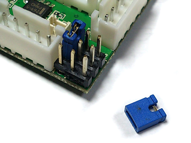
STEP 1:
Turn power off, plug programming line to CN2(
IR Configuration
Port )
STEP 2: Install a jumper to J2
as shown below, turn power on,
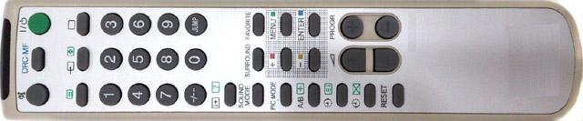
STEP 3: Point
Configuration IR remote to
programming line receiver,
refer to function table listed below and press the
button
of function that you want to set,
STEP 4: Indicator of
programming line flashes according to
new
setting value.
STEP 5: turn power off, remove
jumper on J2, then power on and you are set.
Function tables:
Save
current setting to
PRESET 1: Press number
key "1" on TV remote to save,
|
Available Settings |
Indicator
flashes times |
Description |
|
Save to
PRESET 1 |
1 |
Indicator flashes when setting
is saved
|
Save
current setting to PRESET 2: Press number
key "2" on TV remote to save,
|
Available Settings |
Indicator
flashes times |
Description |
|
Save to
PRESET
2 |
2 |
Indicator flashes when setting
is saved
|
*Once
you've adjusted everything, you can
push "1" or
"2" to save
current setting to PRESET 1
or 2. If you don't do this saving the board remembers
the last settings.
Use saved settings:
Press "ENT" or "SOUND MODE" Key on TV remote to select.
|
Available Settings |
Indicator
flashes times |
Description |
|
Use
PRESET 1
setting |
1 |
|
|
Use
PRESET 2 setting |
2 |
|
|
Use Factory Default Setting
( Read-Only ) |
3 |
To
restore factory
default value in case of setting data is messed up. |
*To
switch between the presets you press either "sound
mode" or "enter" button, once the preset is selected,
switch tank off and remove setup jumper. Switch back on and away you
go.
On-the-move alarm sound On/Off:
Press "Timer
Off(0x3C)"
or "
 "on TV remote to select "on TV remote to select
|
Available Settings |
Indicator
flashes times |
Description |
|
On |
1* |
|
|
Off |
2 |
|
Q:
A:

MADE
IN TAIWAN
|