THIS IS NOT 100% PLUG AND PLAY BOARD, SIMPLE
CHANGE IS NEEDED FOR FULL OPTIONS
(specifications
and design are subject to change without notice)
Overview
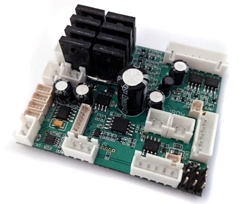
ACK40 series controller is
the successor of successful TK20 series, uses 4-CH conventional
PWM or 10-CH S.BUS RC system to control R/C armored car forward/backward movement,
turning, turret rotation and gun barrel evaluation at variable speed
Ultrasonic
ESC*2 for propulsion motor
22KHz, 8-bit high quality sound with digital sound mixer
Maximum of 5 channel of sound track, main gun,
machine gun, turret rotate, gun barrel elevation and engine sound can be
generated at the same time
3W
sound output power
0.8A BEC
EPM*2
for gun elevation(EPM1) and turret rotation/gun traverses(EPM2)
Wide operating voltage rage, from 7.2 to 12V, support 3S
Li-Po battery
Support air-soft gun with sound synchronization
Support TAMIYA and HL IR
battle unit and format
Support
RealRecoil servo port
Support Recoil Solenoid for 2nd Machine Gun( MG2 )
Support gun
barrel stabilizer
Safety shutoff prevents unwanted movement while signal lost
Auto R/C signal detection
Miniature design(60mm X 50mm X 20mm) for 1/25~1/16 R/C Tank
Terminology
Ultrasonic
ESC is the ESC block which switch FET at ultrasonic speed, make motor
rotation very smooth and quite..
EPM ( ESC/PWM
module) is
peripheralwhich can be switched to
ESC or PWM mode, allows the user to
drive
brushed motor or servo motor, in ESC mode, ESC port is enabled, can be
used to drive brushed motor, In PWM mode, PWM port is enabled to driver
servo motor, sound effect stopped when servo motor reach end point, TK40 has 2
EPMs for gun elevation(EPM1) and turret rotation/gun traverses(EPM2),
EPM No.
ESC/Ultrasonic ESC port
PWM port
EPM1
5th and 6th Pin of CN9
J4
EPM2
7th and 8th Pin of CN9
Note:ESC
in EPM2 is
Ultrasonic ESC
J5
RealRecoil
allows you to recreate real gun barrel recoil movement with single & cheap servo
motor
Recoil
Solenoid
allows you to recreate MG/Auto cannon barrel recoil movement with
Solenoid
Proportional Smoker driver smoker fan/compressor speed is proportional to
engine RPM and Load
Variants
Device
ACK40SP
ACK40SPG2
Remote Control System
2.4G RC system with S.BUS
2.4G RC system with S.BUS
Control
Scheme
10-CH
10-CH
User Sound
Programmability
YES
YES
TAMIYA IR battle
Compatible
YES
YES
HL IR battle
Compatible
YES
YES
VsTank IR
battle
Compatible
YES
YES
TAMIYA 1/35
IR battle Compatible
YES
YES
Damage Simulation
on
propulsion motor
YES
YES
Damage Simulation
on turret
rotation
YES
YES
Long range IR battle
(>30M)
YES
YES
Engine Sound Simulation
V2
V2
Neutral Gear
YES
YES
Sound set for
specific tank model
YES
YES
Populsion motor
driver switching frequency
Ultrasonic
Ultrasonic
Propulsion motor
driver Current
20A
20A
Propulsion motor driver
Momentum Effect
(Soft start/stop effect)
with ON/Off Control
YES
YES
Turret Rotation Speed Control
YES
YES
Gun Elevation Speed Control
YES
YES
Gun Elevation
Servo Port
YES
YES
2nd MG sound and Light
effect
YES
YES
AirSoft with Sound Synchronization support
YES
YES
TAMIYA Recoil Unit Support
YES
YES
RealRecoil
YES
YES
Smoker driver
YES
YES
Proportional
Smoker driver
V2
proportional to engine
RPM
and Load
V2
proportional to engine
RPM
and Load
Head Light on/off control
YES
YES
Tank Personalization
YES
YES
LED GUN FLASHER Port
YES
YES
Chassis
Recoil On/Off
Control
YES
YES
Vertical Gun
Barrel Stabilizer
NO
YES
Turret
Heading-Hold
(Horizontal
Gun
Barrel
Stabilizer)
NO
YES
Auto Load
Position
NO
YES
Engine Deck
Level Detection
NO
YES
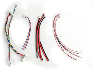
Kit contained
TK40SP board*1,
channel cable*4
TK40SPG2 board*1,
channel cable*4
Price
(USD)
150
249
Release Schedule
Released
Aug.2018
* 20A if to
connect motor from on-board connector, 60A if hardwire motor to PCB pads, 105A
for A1 board
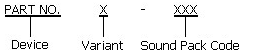
Product
Identification System
Device
ACK40
ACK40 series
Armored Car Controller
Variant
Blank
Standard,
Equal to P Variant in TK60 series
S
Support S.BUS
interface
P
Sound
Programmable
Sound Pack
T1
Tiger I
KT
King Tiger
CH2_V1
Challenger 2
ver. 1
.....
Refer to TK Sound Pack webpage for more
information
Hardware Variants
Variant Code
Description/Notice/Change/New
Features
Release Schedule
-
Standard Specification, 20A current.
Class-A audio amplifier
Released
Software Revisions
Software
Package
Name
Description/Notice/Change/New
Features
Release Schedule
V1 ( S.BUS )
-10-CH
S.BUS control scheme,
- High
resolution (64 Steps) ESC driver.
- Ver.2 Bootloader
- V2
Released
V2( Std PWM )
-4-CH traditional PWM
- High
resolution (16 Steps) ESC driver.
- Ver.2 Bootloader
TBD
Boot loader Revisions
Boot Loader is a application, executed in TK
board, to handles software update, sound pack programming and setting data
update
Version
Description/Notice/Change/New Features
Release Schedule
Ver.2
-Auto Sound pack change detection
-Auto Clean at software update
Released
Accessories
Part Number
Description
Configuration IR REMOTE
For
Tank Personalization function
IR005
Std. IR battle
emitter kit
IR010
High
Power IR battle
emitter kit
CAB001
1.25mm pitch cable
connector for connecting IR LED or Gun Flash LED
HL Cable Set
Motor
Cable *2
Battery Cable *1
Speaker Cable *1
Smoke Unit Cable *1,
Smoke Unit Switch Cable (no
switch) *1
8P Inter-connection Cable *1
Volume Control Cable( no VR ) *1
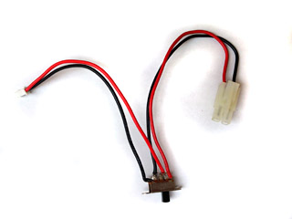
HL Power
Cable
One end to TK20, another end to
battery, one switch in the middle
IR Programming Line
5P connector with IR receiver
& Red LED indicator, and a 2.54mm-pitch Jumper
TBU
BASE
Base and cable to connect TK board to TAMIYA
Battle Unit. a 2.54mm-pitch Jumper is
included
GBS Unit
Gun Barrel Stabilizer unit
4-CH
Conventional PWMmode control
scheme
Booming
Main cannon
FireMG2
Cannon elevation
Turret rotation
Neutral Gear Shift In/Out :
Propulsion
motor does not move when shift to natural gear
Engine sound on/off
Fire MG: Number of burst is controlled by the time of stay.
Head
light control on/off
Tank move
forward and backward
Right and
Left turn
10-CH
S.BUS
mode control
scheme
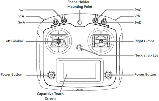
Transmitter: FS-i6S, self-centering VrA
and VrB type Radio
RX:FS-iA10B
Receiver to TK40 board connection
Receiver
TK40SP
CH1
No connection
CH2
No connection
CH3
No connection
CH4
No connection
CH5
No connection
CH6
No connection
CH7
No connection
CH8
No connection
CH9
No connection
CH10
No connection
i.Bus SERVO
CH1
i.Bus SENS
No connection
Layout
Command
S.BUS
Channel
assignment
Right
and Left turn
CH1 (Stick)
Move forward
and backward
CH2 (Stick)
Cannon elevation
CH3
(Stick)
Turret rotation
CH4
(Stick)
SwB: Up
SwC: Center -> Up
Natural Gear Shift In/Out
Assign SwB to CH7
Assign SwC to CH8
SwB: UP
SwC: Center -> Down
Engine start/stop
Assign SwB to CH7
Assign SwC to CH8
SwB: Center
SwC: Center -> Up
NA
Assign SwB to CH7
Assign SwC to CH8
SwB: Center
SwC: Center -> Down
NA
Assign SwB to CH7
Assign SwC to CH8
SwB: Down
SwC: Center -> UP
NA
Assign SwB to CH7
Assign
SwC to CH8
SwB: Down
SwC: Center -> Down
Head
light On/Off
Assign SwB to CH7
Assign SwC to CH8
SwA
UP: Smoke
Unit On
DW: Smoke
Unit Off
Assign SwA to CH5
SwB
NA
Assign SwB to CH6
VrA
UP: Booming Cannon
MID:
DW: FireMG1
Assign VrA to CH9
VrB
UP: N/A
MID:
DW: Fire
MG2
Assign VrB to CH10
Specification
Parameter
Unit
Maximum current of
propulsion motor ESC, connect motor to
on-board connector
20
A
Maximum current of turret and
cannon elevation ESC
6
A
Maximum current of Smoker Driver
6
A
Maximum supply
voltage
11.4
V
Minimum supply
voltage
7.2
V
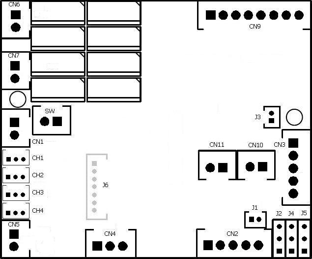
Connector and pin
assignments
Connector
Description
Upper
Hull Functions (CN9) Mode
Airsoft
Tamiya Recoil
MG2
Recoil
Solenoid
SW
Switch Cable
Port
HL tank
already have power switch on battery cable path, so additional switch is
no longer required, just to short pins in this port by jumper
or connect to a switch cable and keep it switched on.
CN1
Battery
Power
1. Battery +
2.
Battery -
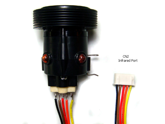
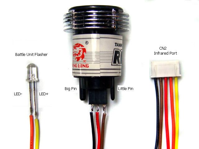
CN2
Infrared Port
1. HBU/TBU +
2. HBU/TBU SIG
3.
HBU/TBU -
4. TBU FLASH LED -
5. TBU FLASH LED +
CN3
Gun Flash
Port
1. Battery +
2. Strobe Trigger
3.
Battery -
4. AirSoft/Recoil Switch
5. AirSoft/Recoil Switch
1. Battery +
2. Strobe Trigger
3.
Battery -
4. TAMIYA Recoil Unit Switch
5. TAMIYA Recoil Unit Switch
1. Battery +
2. Strobe Trigger
3.
Battery -
4. Not connected
5. Not connected
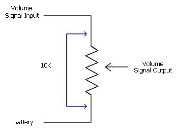
CN4
Sound Volume
1. Volume Signal
Output (
Wiper pin of VR
)
2. Battery -( 1 outside
pin of VR )
3.Volume
Signal
Input (
1 outside pin of VR )
CN5
Speaker
1.
Speaker -
2. Speaker +
CN6
(*x/1)
Ultrasonic ESC1
Connect to
propulsion
motor 1
CN7
(*2/2)
Ultrasonic ESC2
Connect to
propulsion
motor 2
CH1
S.BUS
1. Battery -
2. +5V
3. Signal
CH2
N/A
1. Not Connected
2. Not Connected
3.
Not Connected
CH3
(*2/0)
N/A
1. Not Connected
2. Not Connected
3.
Not Connected
CH4
MG2 LED
Connect to a MG2 LED:
1. N/C
2. LED +
3.
LED -
CN9
Upper Hull Functions
( Turn, Lift, Shoot,
Light)
1. MG1 LED-
2. Head Light LED-
3. MG1 LED+,
Head Light LED+ &
AIRSOFT Motor+
4. AIRSOFT Motor-
5. GUN ELEVATE MOTOR (*0/3)
6. GUN ELEVATE MOTOR
7. TURRET MOTOR (*0/4)
8. TURRET MOTOR(*0/4)
1. MG1 LED-
2. Head Light LED-
3. MG1 LED+,
Head Light LED+ &
TAMIYA
Recoil unit
green Wire
4. TAMIYA Recoil unit white
Wire
5. GUN ELEVATE MOTOR(*0/3)
6. GUN ELEVATE MOTOR(*0/3)
7. TURRET MOTOR(*0/4)
8. TURRET MOTOR(*0/4)
1. MG1 LED-
2. Head Light LED-
3. MG1 LED+,
Head Light LED+ &
MG2
Recoil
Solenoid+
4. MG2
Recoil
Solenoid-
5. GUN ELEVATE MOTOR(*0/3)
6. GUN ELEVATE MOTOR(*0/3)
7. TURRET MOTOR(*0/4)
8. TURRET MOTOR(*0/4)
CN10
(*3/0)
Smoke Unit
Connect to smoke unit
CN11
Smoke Unit Switch
Connect to smoke unit switch
Switch on (Short circuit): smoke unit is
on
Switch off (Open circuit): smoke unit is
off
J1
IR Battle Emitter
Port
To work with IR battle
emitter(IR010)
1. IR LED +
2. IR LED -
J2
(*5)
RealRecoil Servo Port
RealRecoil Servo Port is always
turned ON, no setting is needed to turn it on
1. Signal( White Wire)
2. +5V ( Red Wire)
3. Battery - (Black Wire)
See RealRecoil section in
Assembly Guide
J3
Cannon Flasher Port
1. Cannon Flash
LED +
2. Cannon Flash
LED -
J4
(*1/5)
Gun Elevation Servo Port
1. Battery -
2. +5V
3. Signal
J5
(*3/3)
Turret/Gun
traverse Servo
Port
1. Battery -
2. +5V
3. Signal
J6
Programming and GBS unit Port
To connect TK Programmer or
GBS unit
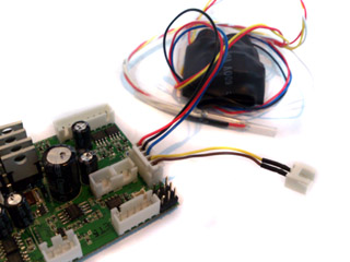
Connection diagram( Click to download full size image )
Installation Guide
Set Upper Hull Functions
(CN9) Mode
to match your tank
hardware configuration (HL AirSoft, or TAMIYA Recoil or MG recoil),
Disconnect RX-18 and plug cables to the same connector on TK board,
Set
Sound Volume to middle
Install
a switch cable (for example, HL Smoke Unit Switch Cable)
to SW connector( Switch Cable Port)
as power switch.
Because HL tank already have power switch on battery cable path, so additional
switch is not required, just to use a jumper to short
pins in SW Cable port or connect a switch cable and keep it switched on.
When high current propulsion motor
are used, such as 400/480 motor,
power switch on battery cable path will not be able to handle,
connect a switch cable (for example, HL Smoke Unit Switch Cable)
to this port
as power switch.
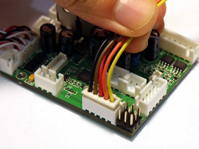
Connect
channel cables to receiver according to RC
mode( See picture "TK series connector and pin assignments" ) . if you are not sure what mode you RC system is, just swap CH2 and CH3 and
try again.
TK40 board has BEC( Battery
eliminate
circuit),
can power receiver through channel cables, no additional battery is needed for
receiver
Set CH1,
2 and 3 trimmer on transmitter to center position, Set CH4 trimmer on
transmitter to most left or right position,
Connect power adaptor( See FAQ )
Switch on TK board and transmitter, you should hear
turret traverse
sound. if not, please contact us.
gently
move CH4(Multi
function control signal 2)
trimmer to center till
turret traverse is gone.
gently
move CH2(Throttle )
trimmer up and down if you hear motor hum sound.
Cannon
firing sound should be generated and
recoil servo should moves when move
CH3 stick to most top position, if not, gently move CH3(Multi
function control signal 2 )
trimmer up and down till
it work correctly.
You are
all set
Disconnect power adaptor and connect battery( make sure that battery is fully
charged).
Installation Video Guide on Internet:
https://www.youtube.com/watch?v=_eIRTIMyl2g
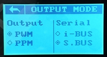
S.BUS setup
Transmitter:
1.Turn on Transmitter i6s and enter setting
function, go to system->output mode, than set Serial to S.BUS
2. Enter aux channel setup, set
channel 5 to SwA, channel 6 to SwD, channel 7 to SwB, channel 8 to SwC, channel
9 to VrA and channel 10 to VrB
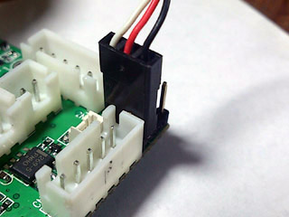
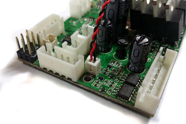
Receiver and control board:
1. Plug connector with S.BUS
label on it into S.BUS port on receiver.
Battle unit installation
TAMIYA battle unit wiring diagram
HL
battle unit installation:
wire CN2 connector to HBU and Flash Unit Flasher as the following
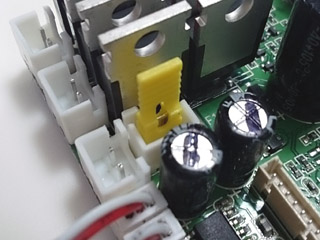
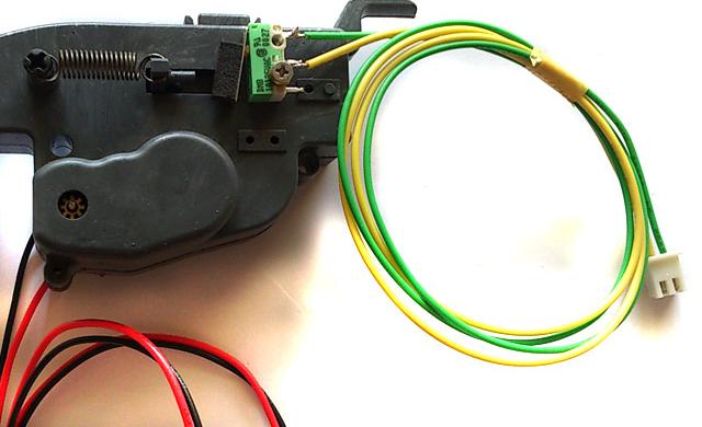
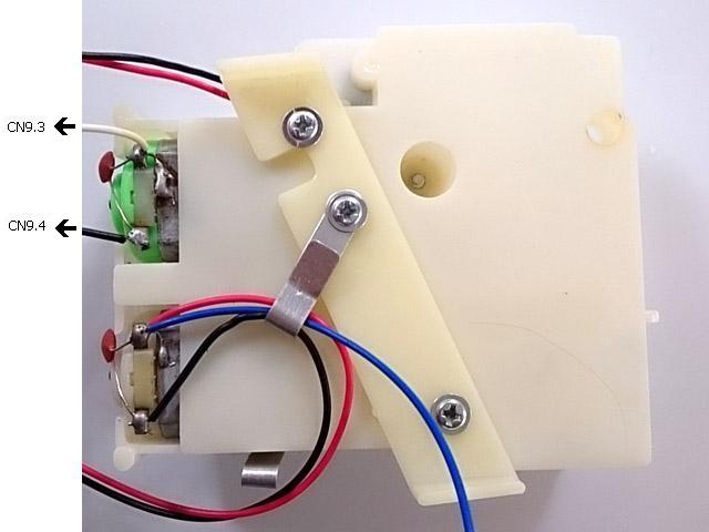
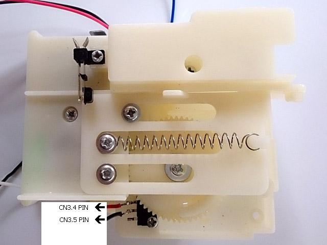
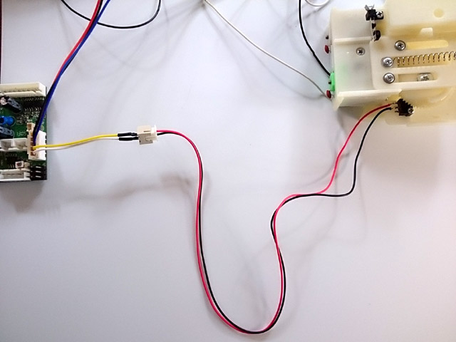
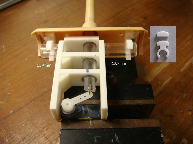
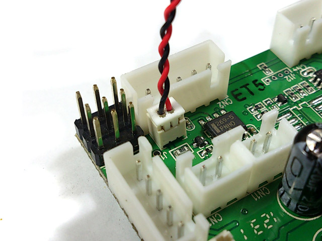
RecoilUnit Installation
TAMIYA recoil unit
installation( -T Version, or set Main Gun
Function Modeto TAMIYA
Recoil MODE )
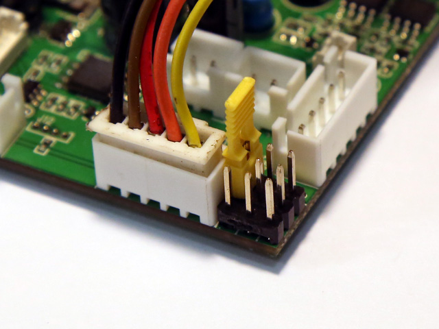
STEP1.
disconnect white and blue wire from recoil unit switch( see arrow in yellow),
add cable connector to recoil switch( see arrow in red ), left green-white-blue cable
not touched ( see arrow in green)
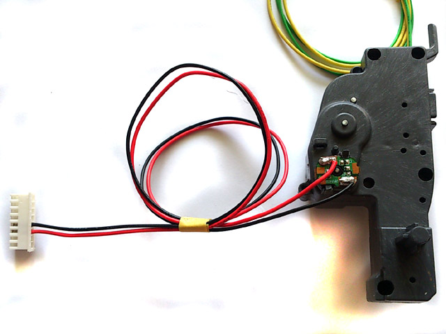
STEP2. green wire and white wire in
green-white-blue cable goes to 3rd pin on CN9 and 4th pin on CN9(see arrow in
green), black and red wire in red-black cable goes to 4th and 5th pin on CN3(see
arrow in red).
HLrecoil unit
installation:
STEP1.
Set Main Gun Function Mode
to
HL Recoil MODE,
STEP2.
Connect detection SW( Pressed-to-Short type ) to 4th and 5th pin on CN3 or via
the plug (Yellow and brown wire) from HL HIGH-TENSION FLASHER. Latest
released HL recoil unit already has detection switch on it.
STEP3.
connect motor - to 4th pin on CN9.connect motor + to 3rd pin on CN9.
Asiatam recoil unit
installation:
STEP1.
Set Main Gun Function Mode
to TAMIYA Recoil
MODE,
STEP2.
Connect Recoil motor + to 3rd pin on CN9.connect motor - to 4th pin
on CN9.
STEP2.
Connect detection SW to 4th and 5th pin on CN3 or via the plug (Yellow and
brown wire) from HL HIGH-TENSION FLASHER
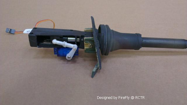
RealRecoil(
Patent Pending)
servo port allows you to recreate real gun barrel recoil movement with single &
cheap servo, what you need to do is to link servo and gun barrel then RealRecoil takes
the rest. direction of servo movement can be set by user, please see section "Tank
Personalization"
GUN FLASHER Installation
HL Hop-up options "HIGH-TENSION
FLASHER" can be easily installed and works with TK20 to simulate gun nuzzle
flash when firing.
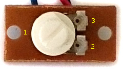
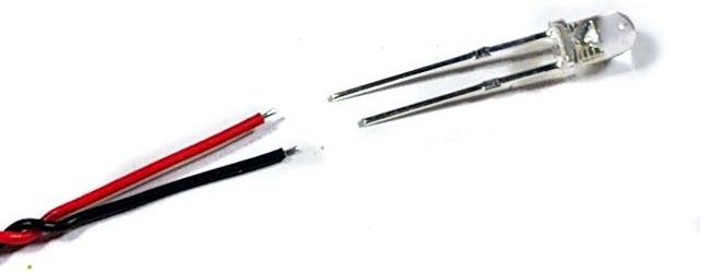
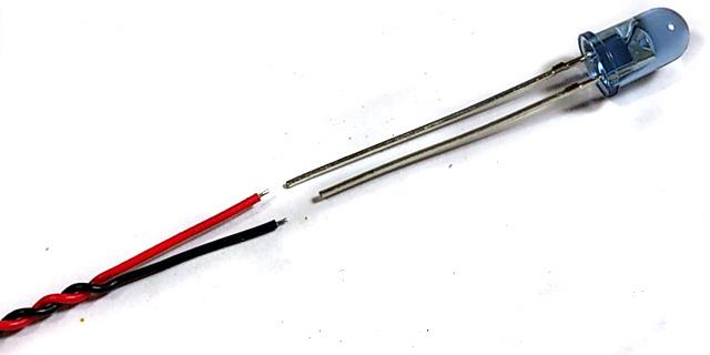
LED GUN FLASHER Installation:
A white LED and cable connector are needed( Part Number
is F003)
Solder color wire (red wire in
this example) to long pin of white LED, black wire(-) to short pin,
Plug cable into J3.
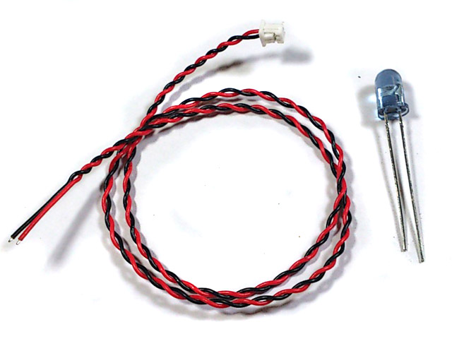
IR battle emitter Installation
An IR LED and cable connector are needed( Part
number is IR005/IR010 ).
Solder color wire (red wire in
this example) to long pin of IR LED, black wire(-) to short pin,
Plug cable into J1.
Tank
Personalization( Patent Pending)
Settings
of TK series board can be changed by
a IR configuration remote
as IR command transmitter, and TAMIYA battle unit(TBU),
Heng-Leog battle
unit(HBU), or our IR configuration line as IR command receiver.
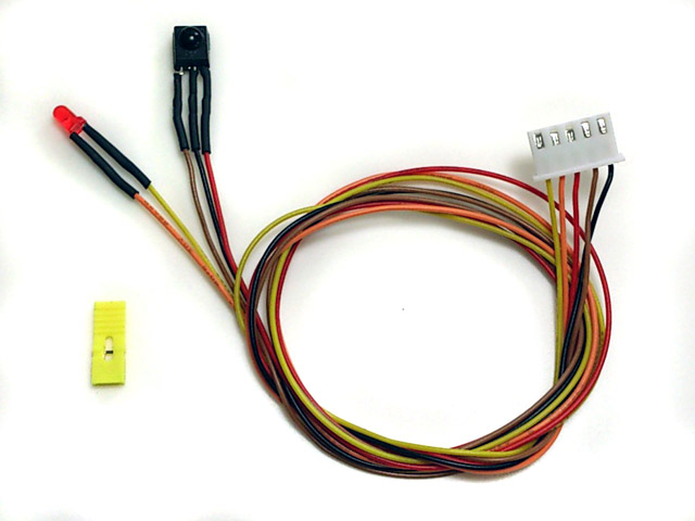
Steps
to change settings:
STEP 1: Turn power off, Turn power off, Turn power off,
STEP 2: Plug programming line/TBU/HBU
through TBU/HBU base into
CN2 Infrared Port ,
STEP 2: Install a jumper to J2
as shown below, Turn power on,
STEP 4:Refer to function table listed below,
point
IR configuration remote to
TBU/HBU/Programming line receiver, and press the
button
of setting that you want to change,
"*"
sign in
function table means
the default setting that is programmed in factory
STEP 5: Indicator on
TBU/HBU flashes according to new
setting value.
STEP 6:
turn power off, remove
jumper on J2, then turn power on and TK board runs
with new settings.
Type of Tank
determines
Battle Date when doing IR battle( See
Variants section
)
Type of
Tank
TankMobility,
Turret rotation and Gun barrel evaluation speed
Note:
Suggested Value, can be changed by Reload Time and
Invulnerability time setting function
Function tables:
Save
current setting to
PRESET 1: Press number
key "1" on IR Configuration Remote to save,
Available Settings
Indicator
flashes times
Description
Save to PRESET 1
1
Indicator flashes when setting
is saved
Save
current setting to PRESET 2: Press number
key "2" on IR Configuration Remote to save,
Available Settings
Indicator
flashes times
Description
Save to PRESET 2
2
Indicator flashes when setting
is saved
*Once
you've adjusted everything, you can
push "1" or
"2" to save
current setting to PRESET 1
or 2. If you don't do this saving the board remembers
the last settings.
Use saved settings:
Press "ENT" or "SOUND MODE" Key on
IR Configuration Remote to select.
Available Settings
Indicator
flashes times
Description
Use PRESET 1
setting
1
UsePRESET 2 setting
2
Use Factory Default Setting
( Read-Only )
3
To
restore factory
default value in case of setting data is messed up.
*To
switch between the presets you press either "sound
mode" or "enter" button, once the preset is selected,
switch tank off and remove setup jumper. Switch back on and away you
go.
Upper Hull Functions
(CN9) Mode:
Press
"POWER" key
on IR Configuration Remote to select
Armor type:
press number
key "9" on IR
Configuration Remote to select
Available Settings
Indicator
flashes times
Description
Heavy Armor
1
Resistance to machine gun
Soft
skin, like Trucks
2*
No resistance to machine gun
Sending IR code when firing
machine gun:
press number
key "6" on IR
Configuration Remote to select
Available Settings
Indicator
flashes times
Description
Not
to send
MG
IR code
1*
To send MG IR code
2
Primary weapon reload time:
press number
key "4" on IR
Configuration Remote to select
Available Settings
Indicator
flashes times
Description
3 seconds
3
4 seconds
4
5 seconds
5
6 seconds
6
7 seconds
7
8 seconds
8
9 seconds
9*
10
seconds
10
11 seconds
11
12
seconds
12
13
seconds
13
14
seconds
14
15
seconds
15
Rounds of Primary weapon:
press number
key "8" on IR
Configuration Remote to select,
Available Settings
Indicator
flashes times
Description
Not
limited
1*
8 rounds
2
16 rounds
3
24 rounds
4
32 rounds
5
40 rounds
6
48 rounds
7
56 rounds
8
64 rounds
9
72 rounds
10
80 rounds
11
88 rounds
12
96 rounds
13
104 rounds
14
112
rounds
15
120
rounds
16
Primary weapon
IR code:
press number key "0" on
IR Configuration Remote to select
Available Settings
Indicator
flashes times
Description
TAMIYA cannon code
1*
For TAMIYA IR battle
HL cannon code
2
For HL IR battle
Repair code
3
For Bergepanzer
application,
damage count decreased by 1 when this IR
code is received, each repair needs 15s, no other vehicle
can damage vehicle that is under this mode
Machine Gun code
4
Vehicle
with MG
Invulnerability time:
Vehicle is Invulnerable during
this period,
press number
key "7" on IR
Configuration Remote to select
Available Settings
Indicator
flashes times
Description
Vehicle can not be recovered from destroyed mode
1
1 second
2
2 seconds
3
3 seconds
4
4 seconds
5
5 seconds
6
6 seconds
7
7 seconds
8
8 seconds
9
9 seconds
10
10
seconds
11*
TAMIYA
Heavy tank
11
seconds
12
12
seconds
13
TAMIYA
Medium tank
13
seconds
14
14
seconds
15
TAMIYA
Light tank
15
seconds
16
Max hit can take:
Press number key "5"
on IR Configuration Remote to select
Available Settings
Indicator
flashes times
Description
1 round
1
2 rounds
2
3 rounds
3
TAMIYA
Light tank
4 rounds
4
5 rounds
5
6 rounds
6
TAMIYA
Medium tank
7 rounds
7
8 rounds
8
9 rounds
9*
TAMIYA
Heavy tank
10
rounds
10
11
rounds
11
12
rounds
12
13
rounds
13
14
rounds
14
15
rounds
15
Function Page Selection:
Press "-/--" Key on IR Configuration Remote to
select.
Available Settings
Indicator
flashes times
Description
Select
settings on Page 1
1*
TK board
goes back to this page after power on
Select settings on Page 2
2
Select settings on Page 3
3
Select settings on Page 4
4
*Text in black means that
setting function is on page1.
Gun elevation EPM (EPM1) Mode:
press "
1"key
on IR configuration remote to select
Available Settings
Indicator
flashes times
Description
ESC Mode
1*
ESC1 enabled, PWM1
disabled
PWM Mode
2
ESC1 disabled, PWM1
enabled
PWM1 Direction:
press "
2"key
on TV remote to select
Available Settings
Indicator
flashes times
Description
Normal
1*
Reversed
2
Turret rotation/gun traverse EPM(EPM2) Mode:
press "
3"key
on IR configuration to select
Available Settings
Indicator
flashes times
Description
ESC Mode
1*
ESC2 enabled, PWM2
disabled
PWM Mode
2
ESC2 disabled, PWM2
enabled
PWM2 Direction:
press "
CH Down"key
on IR configuration remote to select
Available Settings
Indicator
flashes times
Description
Normal
1*
Reversed
2
Engine Sound Throttle input select:
press "
SOUND MODE"key
on IR configuration remote to select
Available Settings
Indicator
flashes times
Description
CH1
1*
Engine sound module
only refer to CH1
CH1 and CH0
2
Engine sound module
only refer to CH1 and CH0
Ultrasonic ESC1 (CN6) input select:
press "CH
UP"key
on IR configuration remote to select
Available Settings
Indicator
flashes times
Description
CH1
1*
When mixer is set to
OFF mode
CH1
controls steering motor(CN6)
CH2
controls propulsion motor(CN7)
CH2
2
When mixer is set to
OFF mode
CH2
controls steering motor(CN6)
CH2
controls propulsion motor(CN7)
GBS LED enable:
press
"TV/VIDEO" or "->[]" Key on
IR Configuration Remote to select
Available Settings
Indicator
flashes times
Description
Enabled
1*
Disabled
2
Elevation Sound Mode:
press
"SOUND Mode" Key on IR
Configuration Remote to
select
Available Settings
Indicator
flashes times
Description
ESC Mode
1*
Elevation Sound follows ESC, will
not stop until ESC is stopped
Servo Mode
2**
Elevation Sound follows servo
movement, stops when reach both end.
Set to this mode when servo
elevation, auto load position and engine deck detection are turned on.
*Default
setting for TK24
**Default setting for TK24G2
Vertical GBS
slow
response gainincrease:
Select page 3 , press number
key "1" on IR Configuration Remote to increase gain
Available Settings
Indicator
flashes times
Description
0
1
:
:
8
9
Vertical GBS
slow
response gain
decrease:
Select page 3 , press number
key "4" on IR Configuration Remote to increase gain
Available Settings
Indicator
flashes times
Description
0
1
:
:
8
9
Vertical GBS
fast
response gainincrease:
Select page 3 , press number
key "2" on IR Configuration Remote to increase gain
Available Settings
Indicator
flashes times
Description
0
1
:
:
8
9
Vertical GBS
fast
response gain
decrease:
Select page 3 , press number
key "5" on IR Configuration Remote to increase gain
Available Settings
Indicator
flashes times
Description
0
1
:
:
8
9
Vertical GBS
servo angle
gainincrease:
Select page 3 , press number
key "8" on IR Configuration Remote to increase gain
Available Settings
Indicator
flashes times
Description
0
1
:
:
8
9
Vertical GBS
servo angle
gain
decrease:
Select page 3 , press number
key "0" on IR Configuration Remote to increase gain
Available Settings
Indicator
flashes times
Description
0
1
:
:
8
9
Engine deck level increase:
Select page 3 , press
"VOL UP" on IR Configuration Remote to increase level
Engine deck level decrease:
Select page 3 , press
"VOL Down" on IR Configuration Remote to decrease level
Engine deck level
Function Enable:Select page 3, press
"MUTE" Key on IR
Configuration Remote to select
Available Settings
Indicator
flashes times
Description
Disable
1
Enable
2*
Engine deck level
detection switch polarity
:Select page 3, press
"JUMP" Key on IR Configuration
Remote to select
Available Settings
Indicator
flashes times
Description
Normal Open switch
1*
Switch come with TK60G2
Normal Close switch
2
TAMIYA switch
Auto Load Position UP:
Select page 3 , press
"CH UP" on IR Configuration Remote to increase level
Auto Load Position Down:
Select page 3 , press
"CH Down" on IR Configuration Remote to decrease level
Auto Load
Position Function Enable:Select page 3, press
"POWER" Key on IR
Configuration Remote to select
Available Settings
Indicator
flashes times
Description
Disable
1
Enable
2*
Ultrasonic ESC
start voltage increase:
Select page 3, press
"3" on IR Configuration Remote to increase level,
indicator flash once each time, indicator flash twice when reach maximum level
Ultrasonic ESC
start voltage decrease:
Select page 3 , press
"6" on IR Configuration Remote to decrease level,
indicator flash once each time, indicator flash twice when reach minimun level
Ultrasonic
ESC start voltage reset to zero:Select page 3, press
"DISPLAY" Key on IR
Configuration Remote to reset start voltage,
indicator flash once every time.
Horizontal GBS motor P gain increase:
Select page 4 , press number
key "1" on IR Configuration Remote to increase gain
Available Settings
Indicator
flashes times
Description
0
1
:
:
8
9
Horizontal GBS motor P gain
decrease:
Select page 4 , press number
key "4" on IR Configuration Remote to increase gain
Available Settings
Indicator
flashes times
Description
0
1
:
:
8
9
Horizontal GBS motor I gain
increase:
Select page 4 , press number
key "2" on IR Configuration Remote to increase gain
Available Settings
Indicator
flashes times
Description
0
1
:
:
8
9
Horizontal GBS motor I gain
decrease:
Select page 4 , press number
key "5" on IR Configuration Remote to increase gain
Available Settings
Indicator
flashes times
Description
0
1
:
:
8
9
Horizontal GBS motor D gain increase:
Select page 4 , press number
key "3" on IR Configuration Remote to increase gain
Available Settings
Indicator
flashes times
Description
0
1
:
:
8
9
Horizontal GBS motor D gain
decrease:
Select page 4 , press number
key "6" on IR Configuration Remote to increase gain
Available Settings
Indicator
flashes times
Description
0
1
:
:
16
17
Turret ESC dead band
increase:
Select page 4 , press number
key "8" on IR Configuration Remote to increase gain
Available Settings
Indicator
flashes times
Description
0
1
:
:
8
9
Turret ESC dead band decrease:
Select page 4 , press number
key "0" on IR Configuration Remote to increase gain
Available Settings
Indicator
flashes times
Description
0
1
:
:
16
17
Status read out and IR battle test via
Configuration IR Remote
Point
Configuration IR remote to TBU/HBU and press key listed below to show
vehicle status or test IR battle function.
No jumper should be installed on J1.
KEY on SONY IR
Configuration Remote
Description
Number Key "1"
To repair vehicle,
damage count decreased by 1
Number Key "2"
Fire
cannon to
vehicle
Number Key "3"
Fire machine gun to
vehicle
Number Key "4"
Number of flash indicate
remain hits
can take
FAQs
Precaution
Read
carefully and fully understand the instructions before commencing assembly.