|
||||||||||||||||||||||||||
|
||||||||||||||||||||||||||
|
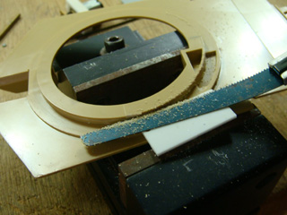
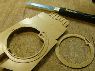
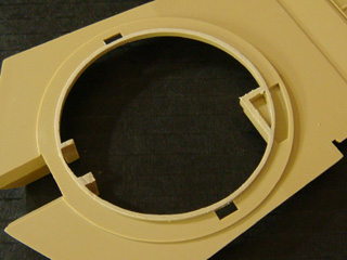
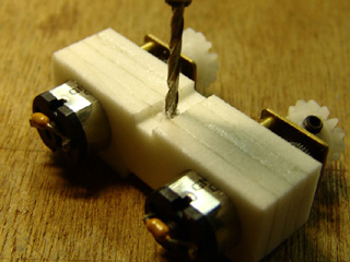
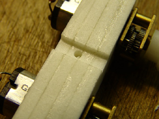
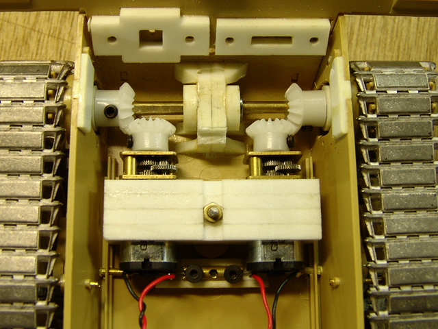
Lower turret
|
|
Turret rotation gear box
|
|
Turret rotation gear ring
|
|
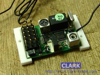
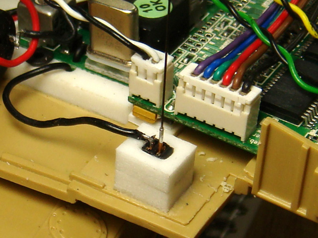
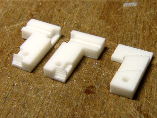
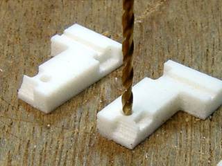
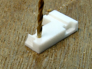
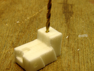
Attaching receiver and anttnna Receiver holder that we are going to use, made by CNC
Clean, drill and tap with 2mm*0.4mm hole
remove receiver cover, install receiver with M2 crew.
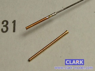
0.3mm black spring wire is used for antenna, solder with 0.5mm copper tube at the end
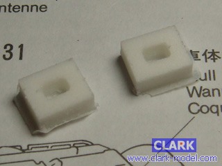
connector holder
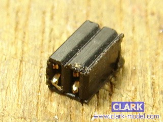
2 pole, 1.25mm pitch connector is used for antenna connector, short 2 lead with solder
push connector into connector holder, wire antenna wire of receiver to a pole of connector, plug spring wire antenna to another pole of connector. spring wire antenna can be unplugged when transporting
|
|
Attaching CSCII
|
|
Attaching LNSII
|
|
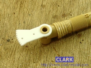
Gun barrel make hole for wring LED
push in gun evaluation gear , no cement is needed,
Trim XXX for evaluation gear movement
<ENG>將砲耳栓黏貼到砲耳軸承座的兩邊上
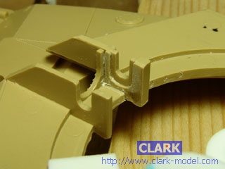
Gun breech part
|
|
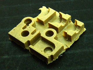
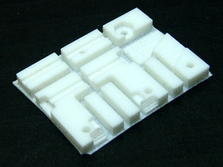
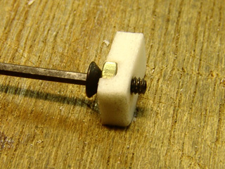
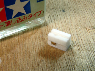
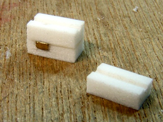
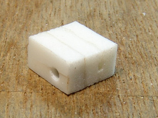
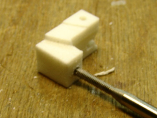
Gun barrel evaluation servo assembly Parts for servo assembly
Drill 1.4mm hole
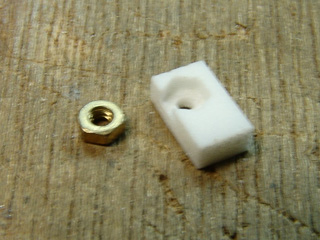
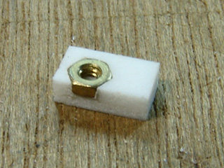
install a nut
tap 1.4mm hole with screw
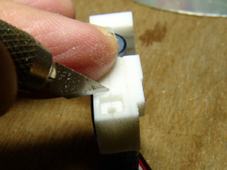
Assembly parts with cement
Drill 1.4mm hole
clean 1.4mm hole with 3~4mm drill head
Assembly parts with cement
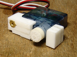
Drill 1.4mm hole and tap it with 2mm *0.4 taper, depth of 3 mm is enough
install servo with 2mm screw
if 1.4mm hole is loosen by over strength, trim the hole and install a nut. and use long screw to install servo
assembly servo gear parts with cement
install servo gear to servo
servo assembly completed
|
|
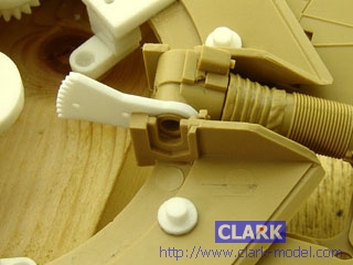
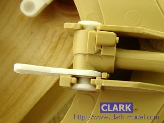
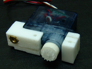
Attaching gun barrel evaluation servo assembly
|
|
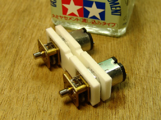
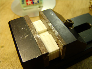
Power Pack( Low Noise, High Torque )
|
|
Power Pack ( High Speed )
|
|
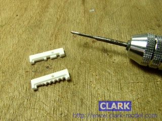
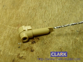
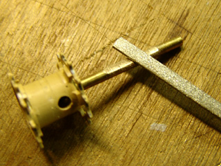
Idler wheel idler wheel arms and bearing
<ENG> 惰輪擺臂上的M1.4螺絲是用於迫緊軸心之用.
<ENG> 將軸心穿入軸承. 並上一點潤滑油在軸心與軸承間使運轉更順暢.
<ENG> 將組好的軸心軸承塞入惰輪殼中
<ENG> 再黏合惰輪
<ENG>裝上惰輪擺臂再用M1.4螺絲鎖緊軸心.
<ENG>將張力調節器外殼的一側打磨成垂直狀態
<ENG>套上模板後鑽孔
<ENG>在張力調節器內側黏上透明墊片後再攻螺紋
<ENG> 把惰輪臂鎖上後安裝惰輪張力調節器
<ENG>磨除定位用凸出物
<ENG> 黏上張力調節器, 並將張力調節器,前裝甲板與惰輪軸活動範圍內干涉部位修除
<ENG>用六角棒穿過惰輪, 確實把惰輪臂鎖緊. 完成如右圖
<ENG>
|
|
Road wheel Trim plastic shaft till A part of B001 can be fitted into right position
Assembly B001
Fit assembled B001 into B002, be award with direction of B002
Fit assembled B001 and B002 into road wheel part
Glue B002 with road wheel by model cement and B001 A part with plastic shaft with quick cement,
Remove hub of road wheel part 2
Fit small rubber tube to shaft and than glue two road wheel parts as the TAMIYA assembly guide said
|
|
Return Roller make hole on center of return roller
Trim return roller shaft as shown on picture for guide horn on track link
to use probe as shaft
Cut one end of shaft
remove spring inside probe
push modified probe to return roller
same modification is applied to small return roller
all of 6 modified return roller
drill hole with assistance of fixture
install shaft holder
install shaft holder to lower hull with cement
|
|
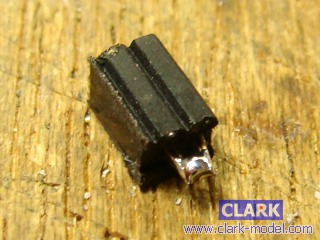
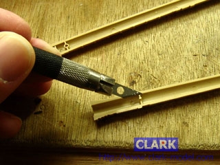
Drive Sprocket
|
|
template
|