|
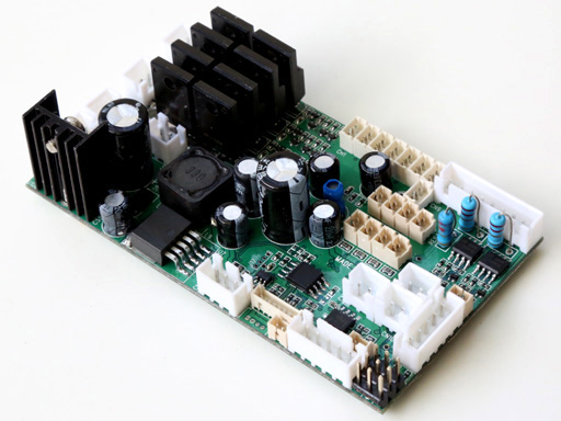
適合用於遙控拖車的整合型電控

 MFK-01
系列控制器使用8動作的遙控系統
行走用電子變速器可達60A
8位元,22KHz採樣率的高音質音效及5音軌數位式混音.
喇叭, 方向燈,引擎音效等可以同時產生
15瓦特音效輸出功
振動馬達模擬引擎的振動 MFK-01
系列控制器使用8動作的遙控系統
行走用電子變速器可達60A
8位元,22KHz採樣率的高音質音效及5音軌數位式混音.
喇叭, 方向燈,引擎音效等可以同時產生
15瓦特音效輸出功
振動馬達模擬引擎的振動
內建BEC,
可以直接供電給接收機
 內建自動斷電機制 內建斷訊安全機制
容易組裝免調整
內建自動斷電機制 內建斷訊安全機制
容易組裝免調整
 可支援
可支援 , , 與2.4G遙控系統
支援
True-HID
燈光效果
支援紅外線尾車控制器
可以使用燒錄器變換音效 與2.4G遙控系統
支援
True-HID
燈光效果
支援紅外線尾車控制器
可以使用燒錄器變換音效
|
|
MFK-01L |
MFK-01 |
|
遙控系統
Radio System |
8-CH AM, FM or 2.4G RC system |
8-CH AM, FM or 2.4G RC system |
|
引擎音效
Engine Sound Simulation
|
Multi
Simple Set Fuzzy Logic
|
Multi
Simple Set Fuzzy Logic
|
|
行走用電子變速器電流
Motor driver Current
|
60A ( 540/550 Motor) *兩路 |
60A ( 540/550 Motor) **兩路 |
|
可以使用燒錄器更換軟體
User-installable software upgrades
via TK programmer |
無 |
有 |
|
可以使用燒錄器變換音效
User-installable
sound pack upgrades
via TK programmer |
無 |
有 |
|
True-HID
燈光效果True-HID Light
effect |
無 |
有 |
|
支援紅外線尾車控制器
Support
Semi-Trailer Controller |
無 |
有 |
|
音效放大器輸出功率
Audio Amplifier |
15W |
15W |
|
內容物
Kit contained |
MFK-01L board *1, channel cable*8 |
MFK-01 board *1, channel cable*8 |
|
參考售價(美元)
Reference Price(USD) |
$150 |
$200 |
|
Product
Identification System |
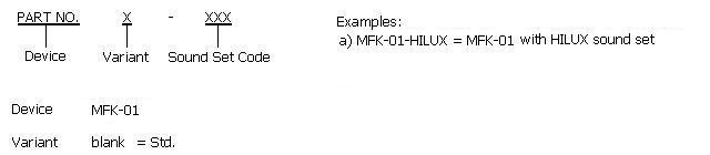
*Sound set code info is on "Sound
Set Code" page
|
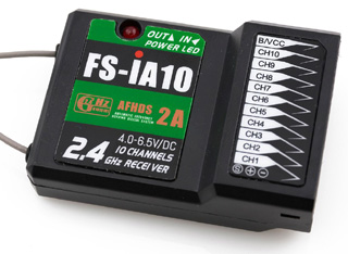
8動操作模式(
以FS-i6s發射機及FS-iA10接收機為例)
8-CH control mode and operation
( Based on FS-i6S transmitter +
FS-iA10 Receiver ) |
Transmitter: FS-i6S, self-centering VrA
and VrB type Radio
Assign SwB to CH7, SwC to CH8, VrA to CH9, VrB to CH10
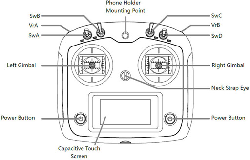
RX:FS-iA10
|
Layout |
Command |
Channel
assignment |
|

CH2
CH1 |
左右轉向
Steering Left and Right
no sound |
CH1 (Stick) |
|

CH2
CH1 |
油門
Move forward
and backward
engine
sound |
CH2 (Stick) |
|

CH4
CH3 |
第五輪及尾車腳
Coupler and
Motorized
support leg
no sound |
CH3
(Stick) |
|

CH4
CH3 |
換擋
Gear Change
gear change
sound??? |
CH4
(Stick) |
|
SwB: Up
SwC: Center -> Up |
室內燈開/關 |
Assign SwB to CH7
Assign SwC to CH8 |
|
SwB: UP
SwC: Center -> Down
|
頭燈開>霧燈開>燈全關
Roof/Aux Light On -> Head Light On -> Fog
Light On -> Lights Off |
Assign SwB to CH7
Assign SwC to CH8 |
|
SwB: Center
SwC: Center -> Up |
打空檔
Natural Gear Shift In/Out |
Assign SwB to CH7
Assign SwC to CH8 |
|
SwB: Center
SwC: Center -> Down |
引擎啟動
Engine start/stop |
Assign SwB to CH7
Assign SwC to CH8 |
|
SwB: Down
SwC: Center -> UP |
迴轉燈警示開/關
Rotating Light On/Off |
Assign SwB to CH7
Assign
SwC to CH8 |
|
SwB: Down
SwC: Center -> Down |
駐車警示燈
Hazard flasher On/Off |
Assign SwB to CH7
Assign SwC to CH8 |
|
VrA |
UP:
喇叭 Horn
(turret sound
driver???)
MID:
Down: 空氣洩壓 Air discharge
( new , use mg2
region)
|
Assign VrA to CH9 |
|
VrB |
UP:
右方向燈 Right Blinker
MID:
Down:
左方向燈 Left Blinker |
Assign VrB to CH10 |
|
Parameter
|
|
Unit
|
|
Maximum current of track ESC |
60 |
A |
|
Maximum current of turret and
cannon elevation ESC |
7 |
A |
|
Maximum current of Smoker Driver |
7 |
A |
|
Maximum supply
voltage |
7.4 |
V |
|
Minimum supply
voltage |
7.2 |
V |
|
On-board audio amplifier
Maximum power |
20 |
W |
MFK series connector and pin assignments

|
Connector
|
Description
|
Note |
|
SW |
Switch Cable Port |
Connect to switch cable
|
|
CH1
|
Receiver Control Signal
|
1. Receiver Signal( White Wire)
2.
Receiver + ( Red Wire)
3. Receiver - ( Black Wire) |
|
CH2
|
Receiver Control Signal
|
1. Receiver Signal( White Wire)
2.
Receiver + ( Red Wire)
3. Receiver - ( Black Wire) |
|
CH3 |
Receiver Control Signal
|
1. Receiver Signal( White Wire)
2.
Receiver + ( Red Wire)
3. Receiver - ( Black Wire) |
|
CH4
|
Receiver Control Signal
|
1. Receiver Signal( White Wire)
2.
Receiver + ( Red Wire)
3. Receiver - ( Black Wire) |
|
CH5
|
Receiver Control Signal
|
1. Receiver Signal( White Wire)
2.
Receiver + ( Red Wire)
3. Receiver - ( Black Wire) |
|
CH6
|
Receiver Control Signal
|
1. Receiver Signal( White Wire)
2.
Receiver + ( Red Wire)
3. Receiver - ( Black Wire) |
|
CH7
|
Receiver Control Signal
|
1. Receiver Signal( White Wire)
2.
Receiver + ( Red Wire)
3. Receiver - ( Black Wire) |
|
CH8
|
Receiver Control Signal
|
1. Receiver Signal( White Wire)
2.
Receiver + ( Red Wire)
3. Receiver - ( Black Wire) |
|
CN1
|
Battery Power
|
1. Battery +
2.
Battery -
|
|
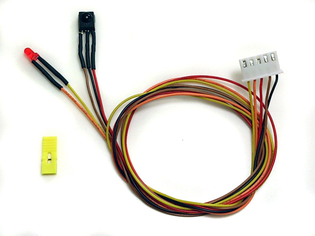
CN2 |
IR Configuration
Port |
1.
IR receiver +
2.
IR receiver SIG
3.
IR receiver -
4.
IR Configuration Indicator
LED -
5. IR
Configuration Indicator
LED + |
|
CN3 |
NA |
|
|
CN4 |
Sound
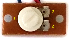
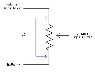
Volume |
1.
Volume Signal
Output (
Wiper pin of VR
)
2. Battery -( 1 outside pin of
VR )
3.
Volume
Signal
Input (
1 outside pin of VR )
 |
|
CN5 |
Speaker |
|
|
CN6
|
Driving Motor 1
|
|
|
CN6-A |
Driving Motor 1
Additional Pad
|
Connect to propulsion motor |
|
CN6-B |
Driving Motor 1
Additional Pad
|
Connect to propulsion motor |
|
CN7
|
Driving Motor 2 |
|
|
CN7-A |
Driving Motor 2
Additional Pad
|
Connect to propulsion motor |
|
CN7-B |
Driving Motor 2
Additional Pad
|
Connect to propulsion motor |
|
CN9 |
Light
Effect Functions |
1. Left blinker LED-
2. Right blinker LED-
3. Left blinker, Right blinker,
Engine Vibration
Motor +
4.
Engine Vibration
Motor
-
5. (HID) HEAD Light LED -
6. (HID) HEAD Light LED +
7. (HID) FOG Light LED -
8. (HID) FOG Light LED +
|
|
CN10 |
Smoke
Unit /
Smoke
Unit Fan |
1. Smoke
Unit + / Smoke Unit Fan +
2. Smoke
Unit - / Smoke Unit Fan -
|
|
CN11 |
Smoke
Unit /
Smoke
Unit Fan switch |
1.
Switch
2.
Switch
|
|
CN12 |
Smoke
Unit
Heater
|
1.
Heater
2.
Heater
|
|
J1 |
Semi-Trailer
controller IR control port |
1. --->2K Resistor -->IR LED +
2. IR LED - |
|
J2 |
Coupler Control?? Servo Port |
1. Signal( White Wire)
2.
+5V ( Red Wire)
3. Battery - (Black Wire) |
|
J3 |
Break Light Port |
1. Break Light LED +
2. Break Light LED - |
|
J4 |
Gear
Shift??
Servo Port |
1. Signal( White Wire)
2.
+5V ( Red Wire)
3. Battery - (Black Wire) |
|
J5 |
Gun Swing?? Servo Port
|
1. Signal( White Wire)
2.
+5V ( Red Wire )
3. Battery - (Black Wire) |
|
J6 |
Programming Port |
To
connect TK Programmer |
|
J7 |
S-BUS Port |
To
connect S-Bus Receiver
1. +5V
2.
Battery -
3.
S-BUS RX
4.
S-BUS TX |
|
J8 |
Engine Deck Level Switch
|
1.
SWITCH
2.
SWITCH
|
|
L1 |
Rotating
Light LED1
|
1. LED +
2. LED - |
|
L2 |
Rotating
Light LED2
|
1. LED +
2. LED - |
|
L3 |
Rotating
Light LED3
|
1. LED +
2. LED - |
|
L4 |
Roof/Aux Light |
1. --> 200R --> LED -
2. LED+ |
|
L5 |
Reverse Light
|
1. LED +
2. LED - |
|
L6 |
Speed
Indicator LED1
|
1. LED +
2. LED - |
|
L7 |
Speed
Indicator LED2
|
1. LED +
2. LED - |
|
L8 |
Speed
Indicator LED3
|
1. LED +
2. LED - |
STK-01 紅外線尾車控制器接腳圖
STK-01
Semi-Trailer Controller
connector and pin
assignments

|
Connector
|
Description
|
Note |
|
SW |
Switch Cable Port |
Connect to a switch |
|
CN1
|
Battery Power
|
1. Battery +
2.
Battery -
|
|
CN2-1 |
IRM Port |
Infrared Receiver Module(IRM) Port
1.
IRM -
2.
IRM SIG
3.
IRM +
|
|
CN2-2 |
IRM Signal Indicator
LED |
1. LED +
2. LED - |
|
CN3 |
AUX light |
1.
--> 2.2 Ohm Resistor --> LED+
2.
LED- |
|
CN4 |
Sound
Volume |
1.
Volume Signal
Output (
Wiper pin of VR
)
2. Battery -( 1 outside pin of
VR )
3.
Volume
Signal
Input (
1 outside pin of VR )
|
|
CN5 |
Speaker |
1.
Speaker -
2.
Speaker +
|
|
CN6
|
ESC1
|
1. Device +
2. Device -
|
|
CN7
|
ESC2 |
1. Device +
2. Device -
|
|
CH1
|
ESC1 control
signal
|
1. Receiver Signal( White Wire)
2.
Receiver + ( Red Wire)
3. Receiver - ( Black Wire) |
|
CH2
|
ESC2 control
signal
|
1. Receiver Signal( White Wire)
2.
Receiver + ( Red Wire)
3. Receiver - ( Black Wire) |
|
CH3 |
ESC3 control
signal |
1. Receiver Signal( White Wire)
2.
Receiver + ( Red Wire)
3. Receiver - ( Black Wire) |
|
CH4
|
ESC3 control
signal |
1. Receiver Signal( White Wire)
2.
Receiver + ( Red Wire)
3. Receiver - ( Black Wire) |
|
CN9-1 |
Left blinker |
1. LED+
2.
LED-
|
|
CN9-2 |
Right blinker |
1.
LED+
2.
LED-
|
|
CN9-3 |
Controlled SW |
1. Device +
2. Device -
|
|
CN9-4 |
ESC3 |
1. Device +
2. Device -
|
|
CN9-5 |
Support legs motor |
TAMIYA Motorized Support Legs
Motor
1.
--> 2.2 Ohm Resistor --> Red Wire
2.
Blue Wire |
|
CN10 |
Reverse light
|
1.
LED+
2.
LED-
|
|
J1 |
IR Emitter Port |
To work
with IR emitter(IR010)
1. IR LED +
2. IR LED - |
|
J2 |
Support legs Servo Port |
1. Battery - (Black Wire)
2.
+5V ( Red Wire)
3. Signal( White Wire) |
|
J3 |
Break light |
1. LED +
2. LED - |
|
J4 |
Servo port
|
1. Battery - (Black Wire)
2.
+5V ( Red Wire )
3. Signal( White Wire) |
|
J5 |
Servo port |
1. Battery - (Black Wire)
2.
+5V ( Red Wire )
3. Signal( White Wire) |
Under construction!
|
To adjust audio amplifier power |
For mass produced MFK board, we
limit the audio amplifier to 5W to prevent speaker in most of
tank model on the market damaged, when larger speaker that can take more
power, such as 10W or 20W is used, do the following to adjust power output to achieve
the loudness and audio quality you need.
|
Personalization( Patent Pending) |
Settings
of MFK series board can be set by
cconfiguration IR remote and programming line(
as follow)
Steps
to set parameters:
STEP 1: Turn power off,
plug programming line
to CN2,
STEP 2: Install a jumper to J2
as shown below, turn power on,
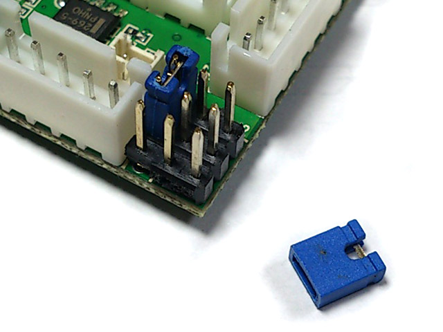
STEP 3: Point
Configuration IR remote to
programming line
receiver,
refer to function table listed below and press the button
of function that you want to set,
STEP 4: Indicator
of programming line flashes according to
the setting value.
STEP 5: turn power off, remove
jumper on J2, then power on and you are set.
Function tables:
Function Table Page Selection:
Press "-/--" Key on TV remote to select. for
TK22G2 only
|
Available Settings |
Indicator
flashes times |
Description |
|
Select
settings on Page 1 |
1* |
MFK board
goes back to this page after power on |
|
Select settings on Page 2
|
2 |
|
|
Select settings on Page 3
|
3 |
|
|
Select settings on Page 4 |
4 |
|
*Text in black means that
setting function is on page1.
Save
current setting to
PRESET 1: Press number
key "1" on TV remote to save,
|
Available Settings |
Indicator
flashes times |
Description |
|
Save to
PRESET 1 |
1 |
Indicator flashes when setting
is saved
|
Save
current setting to PRESET 2: Press number
key "2" on TV remote to save,
|
Available Settings |
Indicator
flashes times |
Description |
|
Save to
PRESET
2 |
2 |
Indicator flashes when setting
is saved
|
*Once
you've adjusted everything, you can
push "1" or
"2" to save
current setting to PRESET 1
or 2. If you don't do this saving the board remembers
the last settings.
Use saved settings:
Press "ENT" or "SOUND MODE" Key on TV remote to select.
|
Available Settings |
Indicator
flashes times |
Description |
|
Use
PRESET 1
setting |
1 |
|
|
Use
PRESET 2 setting |
2 |
|
|
Use Factory Default Setting
( Read-Only ) |
3 |
To
restore factory
default value in case of setting data is messed up. |
*To
switch between the presets you press either "sound
mode" or "enter" button, once the preset is selected,
switch tank off and remove setup jumper. Switch back on and away you
go.
Mixer Mode:
Press  (MUTE) key on TV remote to select. ( change to Vibrate motor strength )
Main Gun Function Mode:
Press
"POWER" key
on TV remote to select
|
Available Settings |
Indicator
flashes times |
Description |
|
TAMIYA RECOIL MODE* |
1* |
To use TAMIYA recoil unit,
CN3,
Pin4:TAMIYA
Recoil Unit Switch
CN3,
Pin5:TAMIYA
Recoil Unit Switch
CN9, Pin3:TAMIYA
Recoil Unit green Wire
CN9, Pin4:TAMIYA
Recoil Unit white Wire
|
|
HL AirSoft MODE |
2 |
To use HL AirSoft,
CN3,Pin4:HL
AirSoft Unit Switch
CN3,Pin5:HL
AirSoft Unit Switch
CN9,Pin3:HL AIRSOFT Motor +
CN9,Pin4:HL
AIRSOFT Motor -
|
|
HL Recoil MODE |
3 |
To use HL Recoil unit,
CN3,Pin4:HL
Recoil Unit Switch
CN3,Pin5:HL
Recoil Unit Switch
CN9,Pin3:HL
Recoil
Motor +
CN9,Pin4:HL
Recoil
Motor -
|
|
Gun elevation servo Mode |
4 |
CN3,Pin4:NC
CN3,Pin5:NC
CN9,Pin3:AUX POWER +
CN9,Pin4:AUX
POWER -
J4.1. Signal( White Wire)
J4.2.
+5V ( Red Wire)
J4.3. Battery - (Black Wire)
*This function
is only available on TK22 |
*Use this mode on Hooben T-55 Tank.
IR
Battle Preset Data: press "MTS" or "A/B" Key on TV remote to select
|
Available Settings |
Indicator
flashes times |
Description |
|
TAMIYA Heavy tank |
1* |
Reload Time = 9 seconds,
Invulnerability time = 10 seconds,
Max. hit can
take = 9 hit. |
|
TAMIYA
Medium tank |
2 |
Reload Time = 5 seconds,
Invulnerability time = 12 seconds,
Max. hit can
take = 6 hits |
|
TAMIYA
Light tank |
3 |
Reload Time = 3 seconds,
Invulnerability time = 15 seconds,
Max. hit can
take = 3 hits. |
|
Heavy Armored Vehicle |
4 |
Invulnerability time = 10 seconds,
Max. cannon hit cam take = 1 hit
Max. machine gun hit can take = 24 hit. |
|
Medium
Armored Vehicle |
5 |
Invulnerability time = 10 seconds,
Max. cannon hit can take = 1 hit
Max. machine gun hit can take = 16 hit. |
|
Light
Armored Vehicle
|
6 |
Invulnerability time = 10 seconds,
Max. cannon hit can take = 1 hit
Max. machine gun hit can take = 8 hit. |
|
HL tank |
7 |
Reload Time = 3 seconds,
Invulnerability time = 10 seconds(Note1)
Max. hit can
take = 5 hits, |
|
Reserved |
8 |
|
Note1: Reference setting for HL
Tank
Momentum effect On/Off: Press "SLEEP(0x36)"
or " "
on TV remote to select "
on TV remote to select
|
Available Settings |
Indicator
flashes times |
Description |
|
Off |
1* |
|
|
ON |
2 |
|
*This function
is only available on TK22
Reload Sound On/Off: Press "Timer
Off(0x3C)"
or "
 "on TV remote to select "on TV remote to select
|
Available Settings |
Indicator
flashes times |
Description |
|
On |
1* |
|
|
Off |
2 |
|
*This function
is only available on TK22
Taking
a hit hull recoil On/Off: Press "JUMP(0x3B)"
on TV remote to select
|
Available Settings |
Indicator
flashes times |
Description |
|
On |
1* |
|
|
Off |
2 |
|
*This function
is only available on TK22
Strength of
taking a hit hull recoil:
Press "CH Up" or
"PROGR +" key
on TV remote to select
|
Available Settings |
Indicator
flashes times |
Description |
|
1 |
1 |
Small( 1 ) to Large( 16
)movement |
|
: |
: |
|
6 |
6* |
|
: |
: |
|
16 |
16 |
Firing
tank gun
hull
recoil On/Off:
Press "SURROUND(0x29)"
on TV remote to select
|
Available Settings |
Indicator
flashes times |
Description |
|
On |
1* |
|
|
Off |
2 |
|
*This function
is only available on TK22
Strength of
firing tank gun
hull
recoil:
Press
"VOL UP" key on TV remote
to select
|
Available Settings |
Indicator
flashes times |
Description |
|
1 |
1 |
Small( 1 ) to Large( 16
)movement |
|
: |
: |
|
6 |
6* |
|
: |
: |
|
16 |
16 |
RealRecoil servo direction:
press "CH down"
or "PROGR -" key
on TV remote to select
|
Available Settings |
Indicator
flashes times |
Description |
|
Normal |
1* |
|
|
Reversed |
2 |
|
Gun elevation servo direction:
press " Teletext
ON(0x3F)" or " " key
on TV remote to select " key
on TV remote to select
|
Available Settings |
Indicator
flashes times |
Description |
|
Normal |
1* |
|
|
Reversed |
2 |
|
*This function
is only available on TK22
Speed
reduction
in damaged state:
press "3"
key on TV remote
to select.
|
Available Settings |
Indicator
flashes times |
Description |
|
0% |
1 |
No mobility damage simulation, Speed is not
reduced when Tank is in damaged state. |
|
-12.5% |
2* |
|
|
-25% |
3 |
|
|
-37.5% |
4 |
|
|
-50% |
5 |
|
|
-62.5% |
6 |
|
|
-75% |
7 |
|
|
-87.5% |
8 |
|
Speed
reduction
in
badly damaged
state:
press "DISPLAY"
or "DRC-MF" key on TV remote to
select.
|
Available Settings |
Indicator
flashes times |
Description |
|
0% |
1 |
No mobility damage simulation, Speed is not
reduced when Tank is in badly damaged state. |
|
-12.5% |
2 |
|
|
-25% |
3* |
|
|
-37.5% |
4 |
|
|
-50% |
5 |
|
|
-62.5% |
6 |
|
|
-75% |
7 |
|
|
-87.5% |
8 |
|
Armor type:
press number
key "9" on TV remote to select
|
Available Settings |
Indicator
flashes times |
Description |
|
Heavy Armor |
1* |
Resistance to machine gun
|
|
Soft
skin, like Trucks |
2 |
No resistance to machine gun
|
Sending IR code when firing
machine gun:
press number
key "6" on TV remote to select
|
Available Settings |
Indicator
flashes times |
Description |
|
Not
to send
MG
IR code
|
1* |
|
|
To send MG IR code |
2 |
|
Primary weapon reload time:
press number
key "4" on TV remote to select
|
Available Settings |
Indicator
flashes times |
Description |
|
3 seconds |
3 |
|
|
4 seconds |
4 |
|
|
5 seconds |
5 |
|
|
6 seconds |
6 |
|
|
7 seconds |
7 |
|
|
8 seconds |
8 |
|
|
9 seconds |
9* |
|
|
10
seconds |
10 |
|
|
11 seconds
|
11 |
|
|
12
seconds |
12 |
|
|
13
seconds |
13 |
|
|
14
seconds |
14 |
|
|
15
seconds |
15 |
|
Rounds of Primary weapon:
press number
key "8" on TV remote to select,
|
Available Settings |
Indicator
flashes times |
Description |
|
Not
limited |
1* |
|
|
8 rounds |
2 |
|
|
16 rounds |
3 |
|
|
24 rounds |
4 |
|
|
32 rounds |
5 |
|
|
40 rounds |
6 |
|
|
48 rounds |
7 |
|
|
56 rounds |
8 |
|
|
64 rounds |
9 |
|
|
72 rounds |
10 |
|
|
80 rounds |
11 |
|
|
88 rounds |
12 |
|
|
96 rounds |
13 |
|
|
104 rounds |
14 |
|
|
112
rounds |
15 |
|
|
120
rounds |
16 |
|
Primary weapon
IR code:
press number key "0" on TV
remote to select
|
Available Settings |
Indicator
flashes times |
Description |
|
TAMIYA cannon code |
1* |
For TAMIYA IR battle |
|
HL cannon code |
2 |
For HL IR battle |
|
Repair
code
|
3 |
For Bergepanzer
application,
damage count decreased by 1 when this IR
code is received, each repair needs 15s, no other vehicle
can damage vehicle that is
under this mode |
|
Machine Gun code |
4 |
Vehicle
with MG |
Invulnerability time:
Vehicle is Invulnerable during
this period,
press number
key "7" on TV remote to select
|
Available Settings |
Indicator
flashes times |
Description |
|
Vehicle can not be recovered from destroyed mode |
1 |
|
|
1 second |
2 |
|
|
2 seconds |
3 |
|
|
3 seconds |
4 |
|
|
4 seconds |
5 |
|
|
5 seconds |
6 |
|
|
6 seconds |
7 |
|
|
7 seconds |
8 |
|
|
8 seconds |
9 |
|
|
9 seconds |
10 |
|
|
10
seconds |
11* |
TAMIYA
Heavy tank |
|
11
seconds
|
12 |
|
|
12
seconds |
13 |
TAMIYA
Medium tank |
|
13
seconds |
14 |
|
|
14
seconds |
15 |
TAMIYA
Light tank |
|
15
seconds |
16 |
|
Max hit can take:
Press number key "5"
on TV remote to select
|
Available Settings |
Indicator
flashes times |
Description |
|
1 round |
1 |
|
|
2 rounds |
2 |
|
|
3 rounds |
3 |
TAMIYA
Light tank |
|
4 rounds |
4 |
|
|
5 rounds |
5 |
|
|
6 rounds |
6 |
TAMIYA
Medium tank |
|
7 rounds |
7 |
|
|
8 rounds |
8 |
|
|
9 rounds |
9* |
TAMIYA
Heavy tank |
|
10
rounds |
10 |
|
|
11
rounds |
11 |
|
|
12
rounds |
12 |
|
|
13
rounds |
13 |
|
|
14
rounds |
14 |
|
|
15
rounds |
15 |
|
GBS LED enable:
press
"TV/VIDEO" or "->[]" Key on TV
remote to select
|
Available Settings |
Indicator
flashes times |
Description |
|
Enabled |
1* |
|
|
Disabled |
2 |
|
Horizontal GBS motor Speed gain increase:
Select page 4 , press number
key "1" on TV remote to increase gain
|
Available Settings |
Indicator
flashes times |
Description |
|
0 |
1 |
|
|
: |
: |
|
|
8 |
9 |
|
Horizontal GBS motor Speed gain
decrease:
Select page 4 , press number
key "4" on TV remote to increase gain
|
Available Settings |
Indicator
flashes times |
Description |
|
0 |
1 |
|
|
: |
: |
|
|
8 |
9 |
|
Horizontal GBS motor Start gain
increase:
Select page 4 , press number
key "2" on TV remote to increase gain
|
Available Settings |
Indicator
flashes times |
Description |
|
0 |
1 |
|
|
: |
: |
|
|
8 |
9 |
|
Horizontal GBS motor Start gain
decrease:
Select page 4 , press number
key "5" on TV remote to increase gain
|
Available Settings |
Indicator
flashes times |
Description |
|
0 |
1 |
|
|
: |
: |
|
|
8 |
9 |
|
Horizontal GBS motor Stop gain increase:
Select page 4 , press number
key "3" on TV remote to increase gain
|
Available Settings |
Indicator
flashes times |
Description |
|
0 |
1 |
|
|
: |
: |
|
|
8 |
9 |
|
Horizontal GBS motor Stop gain
decrease:
Select page 4 , press number
key "6" on TV remote to increase gain
|
Available Settings |
Indicator
flashes times |
Description |
|
0 |
1 |
|
|
: |
: |
|
|
16 |
17 |
|
Horizontal GBS
sensitive
increase:
Select page 4 , press number
key "8" on TV remote to increase gain
|
Available Settings |
Indicator
flashes times |
Description |
|
0 |
1 |
|
|
: |
: |
|
|
8 |
9 |
|
Horizontal GBS
sensitive
decrease:
Select page 4 , press number
key "0" on TV remote to increase gain
|
Available Settings |
Indicator
flashes times |
Description |
|
0 |
1 |
|
|
: |
: |
|
|
16 |
17 |
|
Vertical GBS
slow
gain
increase:
Select page 3 , press number
key "1" on TV remote to increase gain
|
Available Settings |
Indicator
flashes times |
Description |
|
0 |
1 |
|
|
: |
: |
|
|
8 |
9 |
|
Vertical GBS
slow
gain
decrease:
Select page 3 , press number
key "4" on TV remote to increase gain
|
Available Settings |
Indicator
flashes times |
Description |
|
0 |
1 |
|
|
: |
: |
|
|
8 |
9 |
|
Vertical GBS
fast
gain
increase:
Select page 3 , press number
key "2" on TV remote to increase gain
|
Available Settings |
Indicator
flashes times |
Description |
|
0 |
1 |
|
|
: |
: |
|
|
8 |
9 |
|
Vertical GBS
fast
gain
decrease:
Select page 3 , press number
key "5" on TV remote to increase gain
|
Available Settings |
Indicator
flashes times |
Description |
|
0 |
1 |
|
|
: |
: |
|
|
8 |
9 |
|
Vertical GBS
servo angle
gain
increase:
Select page 3 , press number
key "8" on TV remote to increase gain
|
Available Settings |
Indicator
flashes times |
Description |
|
0 |
1 |
|
|
: |
: |
|
|
8 |
9 |
|
Vertical GBS
servo angle
gain
decrease:
Select page 3 , press number
key "0" on TV remote to increase gain
|
Available Settings |
Indicator
flashes times |
Description |
|
0 |
1 |
|
|
: |
: |
|
|
8 |
9 |
|
Engine deck level
increase:
Select page 3 , press
"VOL UP" on TV remote to increase level
Engine deck level
decrease:
Select page 3 , press
"VOL Down" on TV remote to decrease level
Engine deck level
Function Enable:
Select page 3, press
"MUTE" Key on TV
remote to select
|
Available Settings |
Indicator
flashes times |
Description |
|
Disable |
1 |
|
|
Enable |
2* |
|
Auto Load Position UP:
Select page 3 , press
"CH UP" on TV remote to increase level
Auto Load Position
Down:
Select page 3 , press
"CH Down" on TV remote to decrease level
Auto Load
Position Function Enable:
Select page 3, press
"POWER" Key on TV
remote to select
|
Available Settings |
Indicator
flashes times |
Description |
|
Disable |
1 |
|
|
Enable |
2* |
|
|